Electrical Specifications
This page outlines the electrical specs and safe operating parameters for the OV20i camera, including power requirements, I/O behavior, pin assignments, and current limits.
Power Requirements
- Input Voltage: 19–24 VDC regulated power supply
- Current Draw: 1 A (typical)
- Power Draw: ~10 W typical
- Recommended Power Supply: 24 VDC, 1 A (minimum)
Power Connector:
- M12 A-coded, 17-pin male connector
- Only pins 5, 6 (GND) and 13, 14 (VIN) are used for power
Digital I/O Specs
The OV20i supports 5 digital I/O lines through the power I/O connector:
| Type | Lines | Logic | Current Rating |
|---|---|---|---|
| Inputs | 3 | NPN-compatible (sinking logic) | – |
| Outputs | 2 | NPN open collector | 100 mA max per line |
| Trigger Input | 1 | Pull to GND to activate | – |
- Output Protection: Overcurrent protection with internal thermal fuse
- DIO GND: Must be tied to PLC/system ground for reliable input detection
warning
Digital outputs (DO0 / DO1) are NPN open-collector, sinking only. They pull the line to GND when active and cannot source +24 V. An external pull-up or load to +24 V must be provided for proper operation.
I/O Connector Pinout (M12 A-Coded, 17-pin)
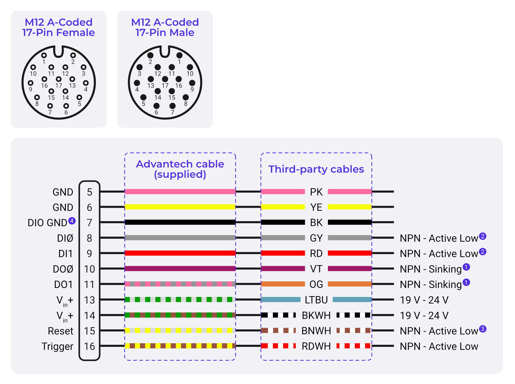
| Pin | Signal | Function |
|---|---|---|
| 5–6 | Power GND | 0V return |
| 7 | DIO GND | Digital I/O return path |
| 8 | Digital Input 0 | Sensor or PLC input (NPN) |
| 9 | Digital Input 1 | Sensor or PLC input (NPN) |
| 10 | Digital Output 0 | NPN open collector output |
| 11 | Digital Output 1 | NPN open collector output |
| 12 | RS232 RX | Optional (not commonly used) |
| 13–14 | Power VIN | +24 VDC supply input |
| 15 | Reset Input | Pull low to reboot (only if instructed) |
| 16 | Trigger Input | Main hardware trigger input (NPN/dry) |
| Others | Reserved / Not Used | No connection |
Communication Ports
| Port | Type | Use |
|---|---|---|
| RJ45 | M12 X-Coded Ethernet | Gigabit network comms |
| Micro USB | USB 2.0 | Emergency IP recovery |
- Micro USB IP:
192.168.55.1(auto when connected to a PC) - Main Camera IP (default):
192.168.0.100
Electrical Design Notes
- Use NPN-compatible sensors/relays when possible.
- Pull to GND to activate inputs.
- Outputs require external 24 V to drive loads.
- Do not exceed 100 mA per output line.
- Always connect DIO GND to external system GND for reliable operation.
Protection & Safety
- Built-in thermal fuse protects DIO GND return
- Ensure proper grounding to prevent floating inputs or noise
- Outputs are floating unless active (NPN open collector)