- 12 May 2025
- Print
- PDF
Ethernet/IP - Switching Recipes
- Updated on 12 May 2025
- Print
- PDF
This section outlines the process for changing the recipe in the camera using PLC logic. Each step and corresponding action are detailed to ensure proper integration and functionality.
Timing Diagram
The timing diagram illustrates the sequence of operations within the camera system, highlighting how various signals interact—how one signal triggers another and how the process moves through stages like Trigger, RecipeSwitchRequest and RecipeSwitchAck. The shifts between high and low states in these signals represent changes in the camera's operation, providing insight into the timing and dependencies of each step in the process.
.png)
Breakdown of the Timing Diagram
Busy:
The "Busy" signal shows whether the system is engaged in a process. It starts low (inactive), goes high when the process begins, and stays high throughout the entire operation. Once the operation is complete, the signal returns low, indicating the system is no longer busy and is ready for the next task.
TriggerRdy (Trigger Ready):
This signal indicates when the system is ready to receive a trigger command. The signal starts high, indicating readiness, and then goes low during the operation, remaining low until the system has completed its current task. At the end of the process, the signal goes high again, indicating that the system is ready for the next trigger.
RecipeSwitchAck (Recipe Switch Acknowledge):
The "Recipe Switch Acknowledge" signal confirms that a recipe switch request has been processed by the system. The signal goes high briefly to acknowledge the request, then returns low, indicating that the acknowledgement process is complete.
RecipeSwitchRequest:
This signal initiates a recipe switch. The signal goes high to request a recipe change and stays high for a short duration, allowing the system to register the request. Once the system has acknowledged the request and begun processing it, the signal returns low, completing the request cycle.
The Busy signal tracks whether the system is occupied, while TriggerRdy shows when the system is ready to accept new commands. The RecipeSwitchRequest signal initiates a recipe switch, and RecipeSwitchAck confirms that the switch has been accepted and processed.
This sequence ensures that recipe switches are handled smoothly and are critical in ensuring that the system operates without conflicts, allowing for smooth transitions between different operational states.
Program the logic using a similar example, PFA the logic attached.

Warning
Make sure the PLC is only sending a recipe switch request when needed, since setting recipe switch high will block triggering.
Steps to Change Recipe
Connect the Camera to the PLC. Refer to Ethernet/IP - Establishing Communication.

1. Moving the Recipe Value:
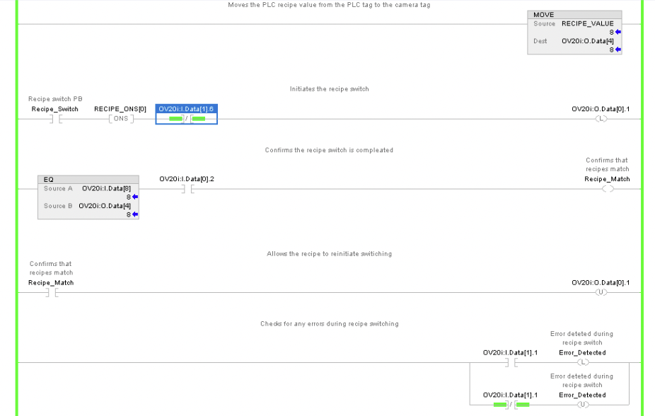
A MOVE instruction transfers the current recipe value from a PLC tag to the camera tag (OV20i:O.Data[4]). This action ensures that the correct recipe data is sent to the camera for processing.
2. Initiating the Recipe Switch:
The process begins with activating the "Recipe_Switch" push button (PB). This action triggers a one-shot (ONS) signal, which initiates the recipe switch by setting the OV20i:O.Data[0].1 output bit high. This output is likely connected to the camera system to begin the recipe-switching process.
3. Confirming Recipe Switch Completion:
Once the camera processes the recipe switch, the system waits for confirmation. The OV20i:I.Data[0].2 input bit goes high to indicate that the recipe switch is complete.
Simultaneously, the system compares the current recipe data (OV20i:I.Data[8]) with the expected recipe value (OV20i:O.Data[4]) using an EQ (Equal) instruction. If the values match, the Recipe_Match bit is set high, confirming that the correct recipe has been loaded.
4. Allowing Re-initiation:
After confirming the match, the system allows for reinitiation of the recipe switching process by resetting the OV20i:O.Data[0].1 output bit. This reset ensures that the system is ready for the next recipe switch command.
5. Error Detection:
The ladder logic also includes error detection mechanisms. If an error occurs during the recipe switch process, it is detected by monitoring the OV20i:I.Data[1].1 input bit. The error is flagged by setting the Error_Detected bit high, which can be used to trigger an alert or halt the process until the issue is resolved.
Summary of Key Points
Camera Connection: Ensure proper connection between the camera and PLC.
Recipe Number: Move the desired recipe number to Camera_1:O.Data[4].
RECIPE_SWITCH Trigger: Use Recipe_ONS to trigger the switch while ensuring the camera is not busy (Camera_1:I.Data[1].6).
Latch Recipe Switch Request: Set and latch Camera_1:O.Data[0].1 for the switch request.
Verify Recipe and Acknowledge: Confirm match between Camera_1:I.Data[8] and Camera_1:O.Data[4] and check Camera_1:I.Data[0].2.
Unlatch Request: Unlatch Camera_1:O.Data[0].1 after confirmation.
Error Monitoring: Watch for Camera_1:I.Data[1].1 to handle any errors.
Recipe Switching and Error Handling
This section outlines the process of switching recipes in the camera system and monitoring the status to ensure successful integration with the PLC logic. Each signal and its corresponding action are explained to maintain proper functionality and error management.
RECIPE_SWITCH (BOOL)
Function: Initiates the recipe switch process.
Description: This tag acts as a control signal from the PLC to start the recipe change sequence. When activated, it triggers the sequence that selects and applies a new recipe on the camera.
Recipe_ONS
Function: Provides a one-shot signal to ensure the recipe switch request is processed only once.
Description: The Recipe_ONS generates a single pulse when the RECIPE_SWITCH signal transitions from low to high. This prevents multiple requests from being sent due to signal fluctuations or noise, ensuring that the recipe switch is processed correctly.
Camera_1:I.Data[1].6 (Busy)
Function: Indicates that the camera is busy processing the recipe switch request.
Description: This bit is set high when the camera is actively processing the recipe switch. It ensures that no other operations are initiated until the recipe switch is complete. The system must wait for this bit to go low before starting any new process.
Camera_1:O.Data[0].1 (Recipe Switch Request)
Function: Sends the recipe switch request to the camera.
Description: This output bit from the PLC initiates the recipe change on the camera. It must be set high to start the process and remain high until the camera acknowledges the switch request.
Camera_1:I.Data[0].2 (Recipe Switch Ack)
Function: Acknowledges the recipe switch request from the camera.
Description: This bit turns high once the camera has received and is processing the recipe switch request. The PLC logic monitors this bit to confirm that the request has been accepted, after which the Recipe Switch Request bit can be unlatched.
Camera_1:I.Data[8] & Camera_1:O.Data[4] (Current Recipe ID and Selected Recipe ID)
Function: Compares the current recipe ID with the selected recipe ID.
Description: The system compares these two data points to ensure that the correct recipe is being applied. If the IDs match, the recipe change is confirmed as successful.
CONFIRM_RECIPES_MATCH (BOOL)
Function: Confirms that the current and selected recipes match.
Description: This tag is set when the comparison between the current and selected recipe IDs shows a match. It confirms that the camera is operating with the correct recipe, allowing the process to continue smoothly.
Camera_1:I.Data[1].1 (Recipe Switch Error)
Function: Indicates an error condition during the recipe switch process.
Description: This bit turns high if an error occurs while switching recipes. It will remain latched until the error is addressed and cleared. Proper error-handling logic should be in place to manage this condition, including resetting the error bit and taking corrective actions.
This setup ensures that recipe switching in the camera system is performed accurately, with the PLC logic handling confirmations and errors to maintain smooth operations.
Summary of Key Signals
RECIPE_SWITCH: Initiates the recipe switch process.
Camera_1:I.Data[1].6: Indicates that the camera is busy processing the recipe switch request. (Busy)
Camera_1:I.Data[0].2: Acknowledgment of the recipe switch from the camera. (Recipe Switch Ack)
Camera_1:O.Data[0].1: Sends the recipe switch request to the camera. (Recipe Switch Request)
Camera_1:O.Data[1].1: Indicates an error during the recipe switch process, which remains latched until the error is cleared. (Recipe Switch Error)
Camera_1:I.Data[8] & Camera_1:O.Data[4]: Used to compare the current recipe ID with the selected recipe ID to confirm that the recipes match. (Current Recipe ID and Selected Recipe ID)
CONFIRM_RECIPES_MATCH: This tag is set when the current and selected recipes match, confirming the correct recipe is in use.
