AI-POWERED DOCS
What do you want to know?
Quick Install Guide
Follow these steps to physically install and power up your OV80i camera for the first time.
What's in the Box
 |  |  |  |  |
|---|---|---|---|---|
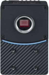
| OV80i Smart Camera | Mounting Plate or Bracket (if ordered) | M12 12-Pin A-Coded Cable (Pigtail or Extension) | M12 8-Pin X-Coded to RJ45 Ethernet Cable | Terminal Block or Power Supply Adapter (optional) |
Required Tools
 |  |  |
|---|---|---|
| 4 mm Hex Key (for mounts) | Small Flathead Screwdriver (for Terminal Block wiring) | 24 V DC Power Source (minimum 1 A output) |
Electrical Connections
Confirm pinout before powering. Incorrect wiring may damage the camera. For full wiring details, see Power + M12 Wiring Guide.
The OV80i uses a 12-pin M12 A-coded connector for all power, I/O, and communication.
- Power Pins:
- Pin 7 = 24V DC (+)
- Pin 8 = GND (−)
You can:
- Use a pigtail cable directly wired to a regulated 24 V DC power supply (minimum 1 A output).
- Or connect via a M12 to Terminal Block Base, which exposes all pins.
Mounting the Camera
- Use the included bracket or a custom rig.
- Ensure the camera is stable and secure.
- Position the camera at the working distance specified for your lens.
The OV80i uses C-mount lenses.
For best results, avoid glare, shadows, or backlight.
Network & Display Setup
- Connect the Ethernet port to a laptop or switch.
- Set your computer to the
10.250.0.Xsubnet to communicate.
The camera ships with:
- Static IP:
10.250.0.100 - DHCP: Off by default (can be enabled in settings)
For emergency access, connect via Micro-USB and open http://192.168.55.1 in a browser (works regardless of Ethernet configuration).
Connect a 1920×1080 display to the HDMI port to view a simplified, read-only HMI for real-time visualization. This is display-only and not interactive.
Network Specifications
Overview.ai cameras (e.g., OV20i, OV80i) are industrial AI vision systems that typically meet the following network specs:
| Feature | Typical Value |
|---|---|
| Interface | 1 Gbps Ethernet |
| Protocol | TCP/IP (often with FTP/MQTT/REST/API) |
| Typical Bandwidth Usage | ~15–50 Mbps per camera (varies by image resolution, frequency, and AI model) |
| Peak Bandwidth | Can briefly spike up to 100–200 Mbps during image uploads or bursts |
Rule of Thumb (per camera):
- Minimum port speed: 1 Gbps
- Recommended per-port buffer: >100 KB to handle bursts
- Uplink/backbone capacity: If aggregating cameras to a switch, uplink should handle ~200–300 Mbps per camera (accounting for overhead)
Power-Up Check
Once powered:
- Power LED (rightmost) should be solid Green.
- Ethernet LED (leftmost) should be Orange if connected.
- Boot completes in ~30 seconds.
Ready to Go
In Chrome or Edge, open: http://10.250.0.100 to access the camera's web interface.
Prefer watching over reading? Check out our video walkthroughs on the homepage for step-by-step visual guides on recipe creation, inspection setup, and integration.
🔗 See Also
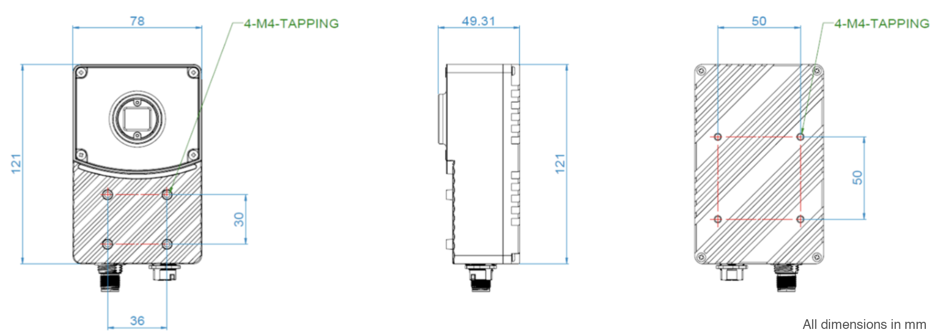
2D Drawings
OV80i Dimensions (mm):
Download 3D Models
Download 3D CAD models for the mounting plate, bracket, and camera body for integration planning:
OV80i: