AI-POWERED DOCS
What do you want to know?
PLC Communication Details (EtherNet/IP)
The OV20i vision system supports real-time communication with EtherNet/IP-based PLCs. This guide explains how to configure cyclic I/O connections, map data structures, and use Overview’s Node-RED tools to access both global and ROI-level inspection results.
See this topic in action: Auto-Integration Builder
For basic connection instructions, see Connect to PLC (EtherNet/IP, PROFINET).
Overview
The OV20i functions as an EtherNet/IP adapter, while your PLC operates as a scanner (or master). Once configured, the devices exchange structured data every cycle using a compact and predictable format.
Supported Features
- Cyclic I/O communication - 20–10,000 ms cycle time support
- Data throughput - Up to 256 bytes in each direction
- Custom data handling - Read/write Node-RED data as part of the active recipe
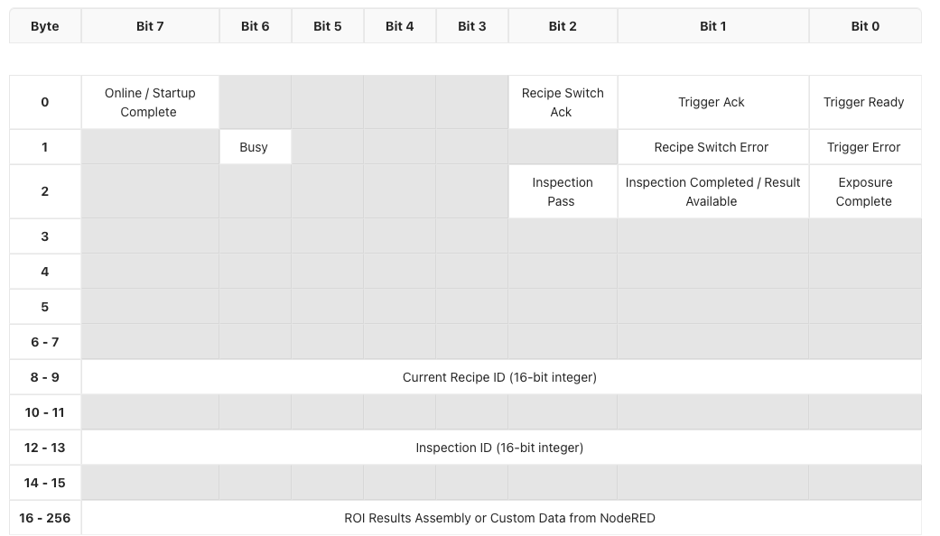
Input Assembly (OV20i → PLC)
The input assembly contains data sent from the OV20i to the PLC on every cycle. This includes system status, inspection results, recipe information, and optional ROI breakdowns.
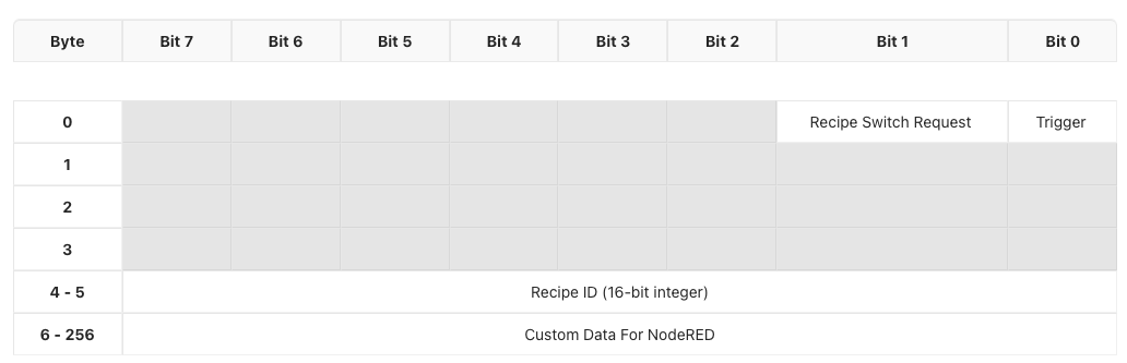
Output Assembly (PLC → OV20i)
The output assembly contains control data sent from the PLC to the OV20i. You can use it to trigger inspections, change recipes, or pass in custom parameters.
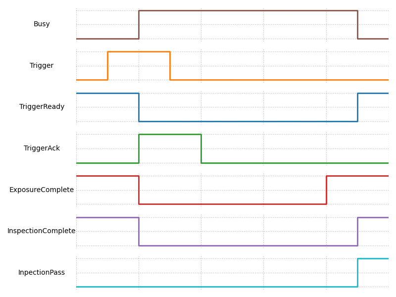
Timing and Handshake Behavior
Custom Data Support
The OV20i can accept or return additional custom data as part of your Node-RED flow.
PLC → OV20i
- Write external flags, thresholds, or counters to influence logic in Node-RED
OV20i → PLC
- Return calculated values, measurements, timestamps, or conditional outputs
Custom data fits into the extended portion of the assemblies, starting after the core signals and recipe info.
ROI Result Breakdown (Classification Recipes Only)
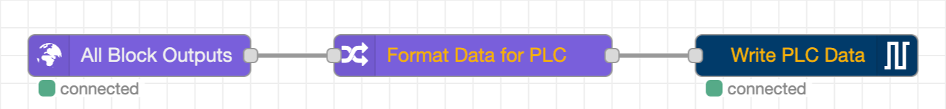
For classification recipes, you can expose per-ROI results to the PLC using Overview’s custom Node-RED node: Format data for PLC.
How it works:
- Placed between All Blocks Output Data and Send Data to PLC in the Node-RED flow
-
Automatically populates a structured ROI region starting at byte 16 in the input assembly
-
Supports up to 4 ROIs per inspection
-
Each ROI includes:
- ROI ID
- Pass/fail bit
- Confidence score
- Reserved bytes for future use
Format Data for PLC Node works with Classification Recipes Only.
Default PLC Tag Reference
This section provides a complete reference of every tag in the Input and Output assemblies, including byte offsets, bit positions, data types, and default values. Use this as the definitive bit map when configuring your PLC program.
Where to View Default Tags in the Camera UI
- Open the OV20i web interface (e.g.,
http://192.168.1.100). - Navigate to Industrial Ethernet in the left sidebar.
- Select your active protocol (EtherNet/IP or PROFINET).
- The page displays the current assembly configuration, including input/output data sizes and the connection status.
- The default tag layout shown on this page corresponds to the tables below.
Input Assembly Tags (OV20i → PLC)
These tags are read by the PLC. The camera writes them every I/O cycle.
Byte 0 -- Status Flags
| Bit | PLC Tag Address | Tag Name | Data Type | Description | Default Value |
|---|---|---|---|---|---|
| 0 | I.Data[0].0 | Trigger Ready | BOOL | Camera is ready to accept a trigger. Must be HIGH before sending a trigger request. | 0 (goes HIGH after startup) |
| 1 | I.Data[0].1 | Trigger Acknowledge | BOOL | Camera has received and accepted the trigger request. | 0 |
| 2 | I.Data[0].2 | Recipe Switch Acknowledge | BOOL | Camera has received and completed the recipe switch request. | 0 |
| 7 | I.Data[0].7 | Online / Startup Complete | BOOL | Camera has finished booting and is online. | 0 (goes HIGH after boot) |
Byte 1 -- Error and Status Flags
| Bit | PLC Tag Address | Tag Name | Data Type | Description | Default Value |
|---|---|---|---|---|---|
| 0 | I.Data[1].0 | Trigger Error | BOOL | An error occurred during the trigger cycle. Latched until cleared. | 0 |
| 1 | I.Data[1].1 | Recipe Switch Error | BOOL | An error occurred during recipe switching. Latched until cleared. | 0 |
| 6 | I.Data[1].6 | Busy | BOOL | Camera is currently processing (inspection running or recipe switching). Do not send new commands while HIGH. | 0 |
Byte 2 -- Inspection Result Flags
| Bit | PLC Tag Address | Tag Name | Data Type | Description | Default Value |
|---|---|---|---|---|---|
| 0 | I.Data[2].0 | Exposure Complete | BOOL | Image exposure has completed. | 0 |
| 1 | I.Data[2].1 | Inspection Completed / Result Available | BOOL | Inspection processing is finished and results are valid. | 0 |
| 2 | I.Data[2].2 | Inspection Pass | BOOL | Final pass/fail result. HIGH = Pass, LOW = Fail. Only valid when Result Available is HIGH. | 0 |
Bytes 3--7 -- Reserved
| Byte(s) | PLC Tag Address | Tag Name | Data Type | Description | Default Value |
|---|---|---|---|---|---|
| 3 | I.Data[3] | Reserved | BYTE | Reserved for future use. | 0x00 |
| 4 | I.Data[4] | Reserved | BYTE | Reserved for future use. | 0x00 |
| 5 | I.Data[5] | Reserved | BYTE | Reserved for future use. | 0x00 |
| 6--7 | I.Data[6]--I.Data[7] | Reserved | BYTE | Reserved for future use. | 0x00 |
Bytes 8--9 -- Current Recipe ID
| Byte(s) | PLC Tag Address | Tag Name | Data Type | Description | Default Value |
|---|---|---|---|---|---|
| 8--9 | I.Data[8]--I.Data[9] | Current Recipe ID | UINT (16-bit) | The ID of the currently active recipe. Compare with O.Data[4] to verify a recipe switch completed. | 0 |
Bytes 10--11 -- Reserved
| Byte(s) | PLC Tag Address | Tag Name | Data Type | Description | Default Value |
|---|---|---|---|---|---|
| 10--11 | I.Data[10]--I.Data[11] | Reserved | BYTE | Reserved for future use. | 0x00 |
Bytes 12--13 -- Inspection ID
| Byte(s) | PLC Tag Address | Tag Name | Data Type | Description | Default Value |
|---|---|---|---|---|---|
| 12--13 | I.Data[12]--I.Data[13] | Inspection ID | UINT (16-bit) | Rolling 16-bit counter that increments with each inspection. Use to correlate results with specific triggers. | 0 |
Bytes 14--15 -- Reserved
| Byte(s) | PLC Tag Address | Tag Name | Data Type | Description | Default Value |
|---|---|---|---|---|---|
| 14--15 | I.Data[14]--I.Data[15] | Reserved | BYTE | Reserved for future use. | 0x00 |
Bytes 16--256 -- ROI Results Assembly / Custom Data from Node-RED
| Byte(s) | PLC Tag Address | Tag Name | Data Type | Description | Default Value |
|---|---|---|---|---|---|
| 16--256 | I.Data[16]--I.Data[256] | ROI Results / Custom Data | BYTE[] | When using the "Format Data for PLC" Node-RED block, this region is populated with structured ROI results. Otherwise available for custom data from Node-RED flows. | 0x00 |
Output Assembly Tags (PLC → OV20i)
These tags are written by the PLC. The camera reads them every I/O cycle.
Byte 0 -- Control Flags
| Bit | PLC Tag Address | Tag Name | Data Type | Description | Default Value |
|---|---|---|---|---|---|
| 0 | O.Data[0].0 | Trigger Request | BOOL | Set HIGH to trigger an inspection. Latch until Trigger Acknowledge (I.Data[0].1) goes HIGH, then unlatch. | 0 |
| 1 | O.Data[0].1 | Recipe Switch Request | BOOL | Set HIGH to request a recipe switch to the ID in O.Data[4]. Latch until Recipe Switch Ack (I.Data[0].2) goes HIGH, then unlatch. | 0 |
Bytes 1--3 -- Reserved
| Byte(s) | PLC Tag Address | Tag Name | Data Type | Description | Default Value |
|---|---|---|---|---|---|
| 1 | O.Data[1] | Reserved | BYTE | Reserved for future use. | 0x00 |
| 2 | O.Data[2] | Reserved | BYTE | Reserved for future use. | 0x00 |
| 3 | O.Data[3] | Reserved | BYTE | Reserved for future use. | 0x00 |
Bytes 4--5 -- Recipe ID
| Byte(s) | PLC Tag Address | Tag Name | Data Type | Description | Default Value |
|---|---|---|---|---|---|
| 4--5 | O.Data[4]--O.Data[5] | Recipe ID | UINT (16-bit) | The recipe ID to switch to. Write the desired recipe number here before setting the Recipe Switch Request bit. | 0 |
Bytes 6--256 -- Custom Data for Node-RED
| Byte(s) | PLC Tag Address | Tag Name | Data Type | Description | Default Value |
|---|---|---|---|---|---|
| 6--256 | O.Data[6]--O.Data[256] | Custom Data for Node-RED | BYTE[] | User-defined data that Node-RED flows can read. Use this region to pass serial numbers, thresholds, part IDs, or any other parameters to the camera. | 0x00 |
Bit Mapping Diagrams
The following text-based diagrams show the complete byte/bit layout for both assemblies. Each row represents one byte (or byte range), and each column represents one bit position (bit 7 on the left, bit 0 on the right).
Input Assembly Bit Map (OV20i → PLC)
Byte │ Bit 7          │ Bit 6  │ Bit 5 │ Bit 4 │ Bit 3 │ Bit 2              │ Bit 1                      │ Bit 0
─────┼────────────────┼────────┼───────┼───────┼───────┼────────────────────┼────────────────────────────┼──────────────────
  0  │ Online/Startup │  ---   │  ---  │  ---  │  ---  │ Recipe Switch Ack  │ Trigger Ack                │ Trigger Ready
     │ Complete       │        │       │       │       │                    │                            │
─────┼────────────────┼────────┼───────┼───────┼───────┼────────────────────┼────────────────────────────┼──────────────────
  1  │  ---           │ Busy   │  ---  │  ---  │  ---  │  ---               │ Recipe Switch Error        │ Trigger Error
─────┼────────────────┼────────┼───────┼───────┼───────┼────────────────────┼────────────────────────────┼──────────────────
  2  │  ---           │  ---   │  ---  │  ---  │  ---  │ Inspection Pass    │ Inspection Completed /     │ Exposure
     │                │        │       │       │       │                    │ Result Available           │ Complete
─────┼────────────────┼────────┼───────┼───────┼───────┼────────────────────┼────────────────────────────┼──────────────────
 3-5 │  ---           │  ---   │  ---  │  ---  │  ---  │  ---               │  ---                       │  ---
─────┼────────────────┼────────┼───────┼───────┼───────┼────────────────────┼────────────────────────────┼──────────────────
 6-7 │                                     Reserved                                                     │
─────┼──────────────────────────────────────────────────────────────────────────────────────────────────────────────────────
 8-9 │                              Current Recipe ID (16-bit unsigned integer)                          │
─────┼──────────────────────────────────────────────────────────────────────────────────────────────────────────────────────
10-11│                                     Reserved                                                     │
─────┼──────────────────────────────────────────────────────────────────────────────────────────────────────────────────────
12-13│                              Inspection ID (16-bit unsigned integer)                              │
─────┼──────────────────────────────────────────────────────────────────────────────────────────────────────────────────────
14-15│                                     Reserved                                                     │
─────┼──────────────────────────────────────────────────────────────────────────────────────────────────────────────────────
16-  │                       ROI Results Assembly or Custom Data from Node-RED                           │
256  │                                                                                                  │
Output Assembly Bit Map (PLC → OV20i)
Byte │ Bit 7 │ Bit 6 │ Bit 5 │ Bit 4 │ Bit 3 │ Bit 2 │ Bit 1                 │ Bit 0
─────┼───────┼───────┼───────┼───────┼───────┼───────┼───────────────────────┼────────────────
  0  │  ---  │  ---  │  ---  │  ---  │  ---  │  ---  │ Recipe Switch Request │ Trigger Request
─────┼───────┼───────┼───────┼───────┼───────┼───────┼───────────────────────┼────────────────
 1-3 │                              Reserved                                │
─────┼──────────────────────────────────────────────────────────────────────────────────────────
 4-5 │                       Recipe ID (16-bit unsigned integer)            │
─────┼──────────────────────────────────────────────────────────────────────────────────────────
 6-  │                       Custom Data for Node-RED                       │
256  │                                                                      │
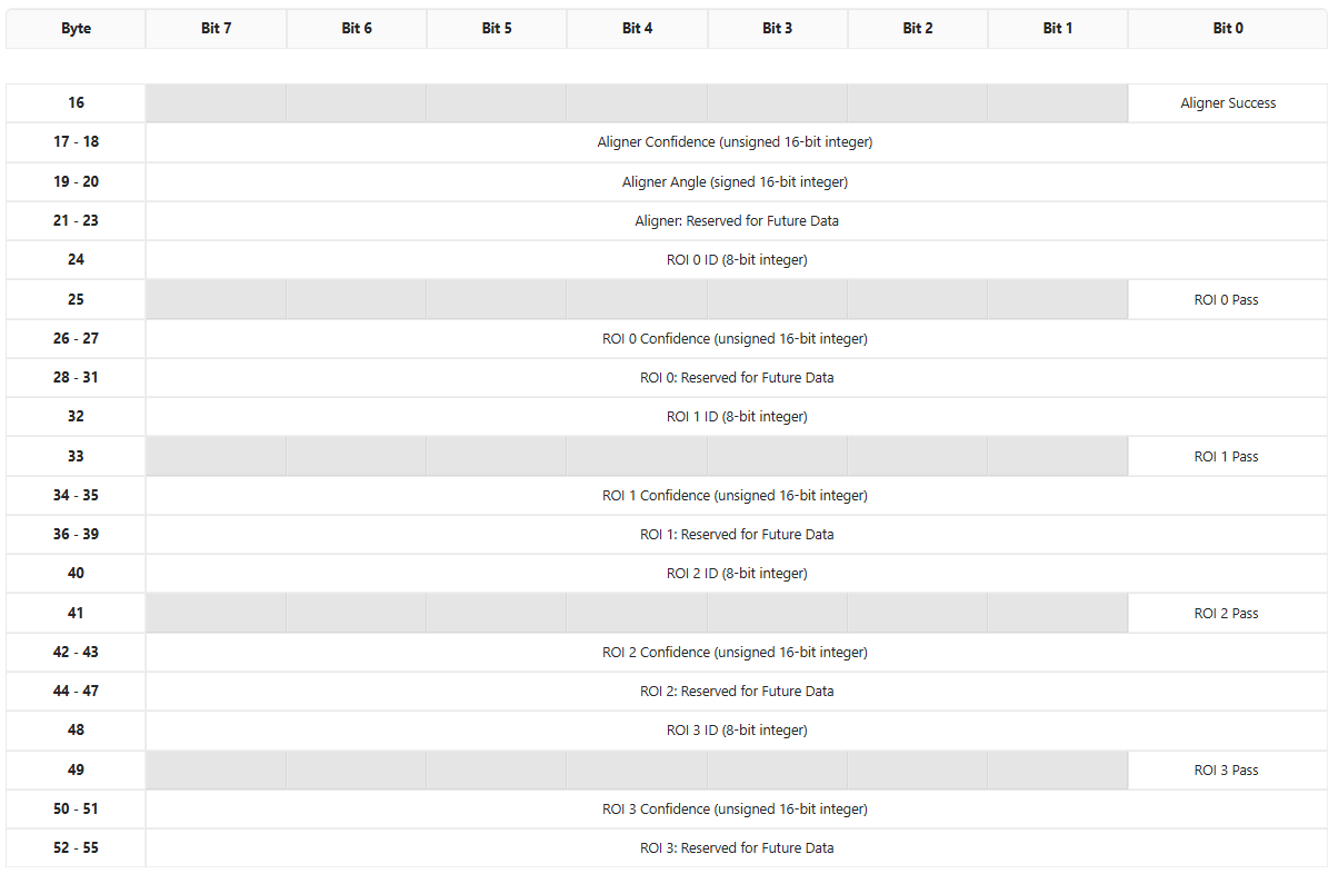
ROI Results Assembly Detail (Bytes 16--55)
When the Format Data for PLC Node-RED block is used with classification recipes, bytes 16+ of the Input Assembly are populated with structured aligner and per-ROI data as follows:
Aligner Section (Bytes 16--23)
| Byte(s) | PLC Tag Address | Tag Name | Data Type | Description |
|---|---|---|---|---|
| 16, bit 0 | I.Data[16].0 | Aligner Success | BOOL | HIGH if the aligner successfully located the part. |
| 17--18 | I.Data[17]--I.Data[18] | Aligner Confidence | UINT (16-bit) | Confidence score of the alignment (0--65535). |
| 19--20 | I.Data[19]--I.Data[20] | Aligner Angle | INT (16-bit, signed) | Matched angle relative to the template. |
| 21--23 | I.Data[21]--I.Data[23] | Reserved (Aligner) | BYTE | Reserved for future aligner data. |
ROI Result Blocks (Bytes 24--55)
Each ROI occupies 8 bytes. Up to 4 ROIs are supported (ROI 0 through ROI 3).
ROI block structure (repeats every 8 bytes):
| Offset within block | Tag Name | Data Type | Description |
|---|---|---|---|
| +0 | ROI ID | UINT8 (8-bit) | Unique numeric identifier of the ROI. |
| +1, bit 0 | ROI Pass | BOOL | HIGH = this ROI passed, LOW = this ROI failed. |
| +2 to +3 | ROI Confidence | UINT (16-bit) | Confidence score for this ROI's classification (0--65535). |
| +4 to +7 | Reserved | BYTE | Reserved for future per-ROI data. |
ROI start addresses:
| ROI | Start Byte | PLC Address Range | ID Address | Pass Address | Confidence Address |
|---|---|---|---|---|---|
| ROI 0 | 24 | I.Data[24]--I.Data[31] | I.Data[24] | I.Data[25].0 | I.Data[26]--I.Data[27] |
| ROI 1 | 32 | I.Data[32]--I.Data[39] | I.Data[32] | I.Data[33].0 | I.Data[34]--I.Data[35] |
| ROI 2 | 40 | I.Data[40]--I.Data[47] | I.Data[40] | I.Data[41].0 | I.Data[42]--I.Data[43] |
| ROI 3 | 48 | I.Data[48]--I.Data[55] | I.Data[48] | I.Data[49].0 | I.Data[50]--I.Data[51] |
Buffer Configuration
Viewing Default Tags in the Camera UI
The default tag layout is defined by the camera firmware and corresponds to the tables above. To view the current configuration:
- Open the OV20i web interface.
- Go to Industrial Ethernet in the left-hand menu.
- Select your protocol (EtherNet/IP or PROFINET).
- The page shows:
- Connection status and device information
- Input and output assembly sizes (up to 256 bytes each direction)
- The EDS or GSDML file download link (which also encodes the default assembly structure)
The EDS file (for EtherNet/IP) and GSDML file (for PROFINET) both define the default data sizes. When you add the camera module in Studio 5000 or TIA Portal, the assembly sizes from these descriptor files determine how many bytes are exchanged each cycle.
Creating a Custom Data Buffer
To send custom data (beyond the default status/result tags) between the camera and PLC, use the "Format Data for PLC" Node-RED block:
- Open Node-RED from the camera web interface (navigate to the Node-RED editor).
- In your recipe flow, place the "Format Data for PLC" node between the "All Blocks Output Data" node and the "Send Data to PLC" node.
- Configure the byte order:
- Little-endian for Allen-Bradley / Rockwell PLCs
- Big-endian for Siemens PLCs
- The block automatically formats classification ROI results into the structured layout starting at byte 16 of the Input Assembly (see the ROI Results Assembly Detail section above).
For completely custom data buffers (not using the default ROI format):
- In your Node-RED flow, use a Function node to construct a
msg.payloadbuffer with your desired byte layout. - Connect it to the "Send Data to PLC" node.
- Your custom bytes will populate the Input Assembly starting at byte 16.
- On the PLC side, read the corresponding
I.Data[16]throughI.Data[256]addresses.
Changing Tag Assignments
The core tags (bytes 0--15 of the Input Assembly and bytes 0--5 of the Output Assembly) are fixed by the camera firmware and cannot be reassigned. These are the system-level signals (trigger, recipe switch, status, errors, recipe ID, and inspection ID).
The configurable region is:
- Input Assembly bytes 16--256: Populated by Node-RED. You control what data goes here by configuring your Node-RED flow. The "Format Data for PLC" block fills this with ROI results by default, or you can write arbitrary data using Function nodes.
- Output Assembly bytes 6--256: Read by Node-RED. You can write any data from the PLC into these bytes, then read them in your Node-RED flow using the appropriate input nodes. This is useful for sending serial numbers, lot IDs, thresholds, or other parameters from the PLC to the camera.
Sending Custom Data from PLC to Camera (Output Assembly)
To pass custom data from the PLC into Node-RED:
- In your PLC program, write values to
O.Data[6]throughO.Data[256]. - In Node-RED on the camera, use the PLC input data nodes to read those bytes.
- Use the values in your flow logic (e.g., thresholds, serial numbers, conditional parameters).
Quick Reference: Tag Address Cheat Sheet
The table below summarizes the most commonly used tags in one place for fast lookup during PLC programming:
| PLC Address | Direction | Signal Name | Usage |
|---|---|---|---|
I.Data[0].0 | Camera → PLC | Trigger Ready | Check before triggering |
I.Data[0].1 | Camera → PLC | Trigger Acknowledge | Unlatch trigger after this goes HIGH |
I.Data[0].2 | Camera → PLC | Recipe Switch Ack | Unlatch recipe request after this goes HIGH |
I.Data[0].7 | Camera → PLC | Online / Startup Complete | Confirm camera is booted |
I.Data[1].0 | Camera → PLC | Trigger Error | Monitor for trigger faults |
I.Data[1].1 | Camera → PLC | Recipe Switch Error | Monitor for recipe switch faults |
I.Data[1].6 | Camera → PLC | Busy | Do not send commands while HIGH |
I.Data[2].0 | Camera → PLC | Exposure Complete | Image captured |
I.Data[2].1 | Camera → PLC | Result Available | Safe to read pass/fail |
I.Data[2].2 | Camera → PLC | Inspection Pass | HIGH = Pass, LOW = Fail |
I.Data[8]--I.Data[9] | Camera → PLC | Current Recipe ID | Verify recipe after switch |
I.Data[12]--I.Data[13] | Camera → PLC | Inspection ID | Correlate results to triggers |
O.Data[0].0 | PLC → Camera | Trigger Request | Latch HIGH to trigger |
O.Data[0].1 | PLC → Camera | Recipe Switch Request | Latch HIGH to switch recipe |
O.Data[4]--O.Data[5] | PLC → Camera | Recipe ID | Set desired recipe number |
O.Data[6]+ | PLC → Camera | Custom Data | User-defined data for Node-RED |
I.Data[16]+ | Camera → PLC | ROI Results / Custom Data | ROI results or custom Node-RED output |