AI-POWERED DOCS
What do you want to know?
Connect to PLC (Ethernet/IP, PROFINET)
This guide shows you how to connect your OV20i camera to industrial PLCs using EtherNet/IP or PROFINET protocols. These connections enable real-time communication for triggering inspections, receiving results, and integrating vision inspection into your automated production systems.
See this topic in action: Auto-Integration Builder
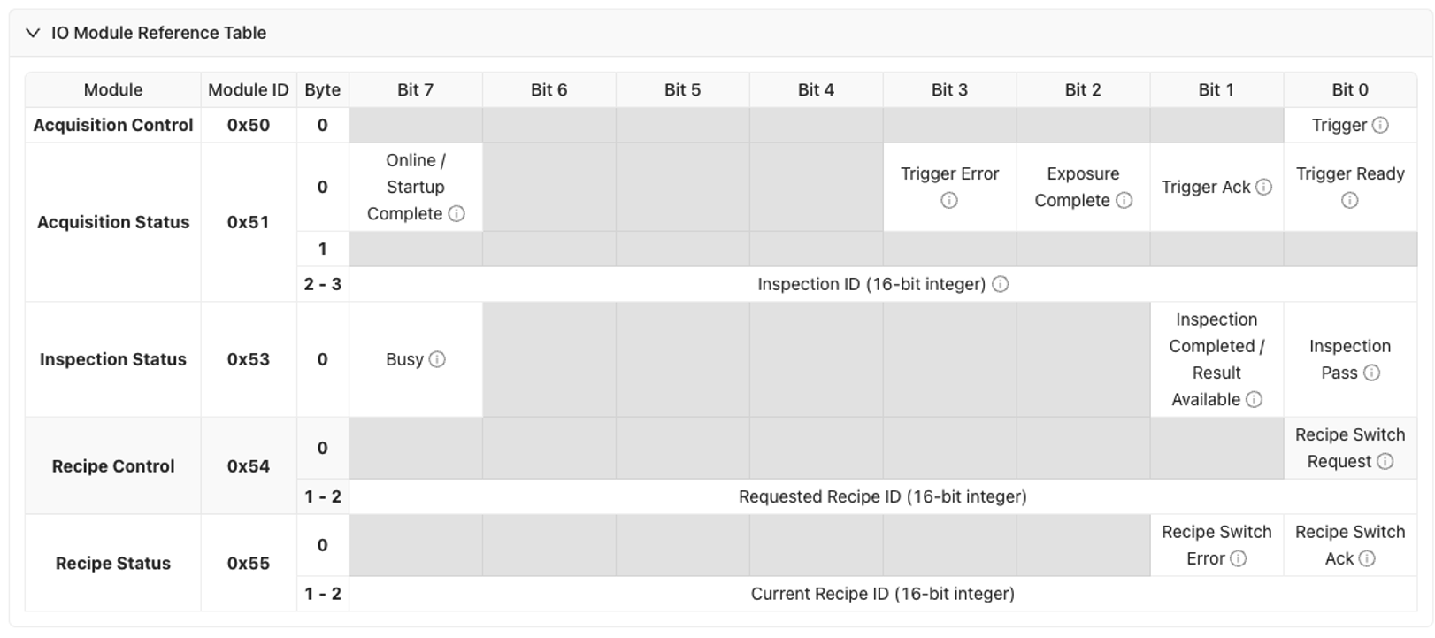
For detailed data mapping and timing information, see PLC Communication Details (EtherNet/IP)
When to Use PLC Communication: When you need to integrate vision inspection with automated production lines, trigger inspections from PLC signals, send pass/fail results to PLCs, or coordinate vision inspection with other automation equipment.
Prerequisites
- OV20i camera system set up and connected to network
- PLC system with EtherNet/IP or PROFINET capability
- Network infrastructure connecting camera and PLC
- Access to PLC programming software (Studio 5000, TIA Portal, etc.)
- Basic understanding of industrial networking concepts
Understanding PLC Communication Protocols
EtherNet/IP
- Used by: Allen-Bradley/Rockwell Automation PLCs primarily
- Benefits: High-speed communication, widely supported, explicit and implicit messaging
- Applications: ControlLogix, CompactLogix, and other Rockwell platforms
- Data Exchange: Cyclic I/O and message-based communication
PROFINET
- Used by: Siemens and other European manufacturers
- Benefits: Real-time deterministic communication, advanced diagnostics
- Applications: Siemens S7 PLCs, various industrial automation systems
- Data Exchange: Cyclic I/O with real-time performance
Part 1: EtherNet/IP Connection
Step 1: Download and Install the EDS File
The EDS (Electronic Data Sheet) file must be installed in Studio 5000 before you can add the OV20i to your PLC project. Without it, the camera will not appear in the module catalog.
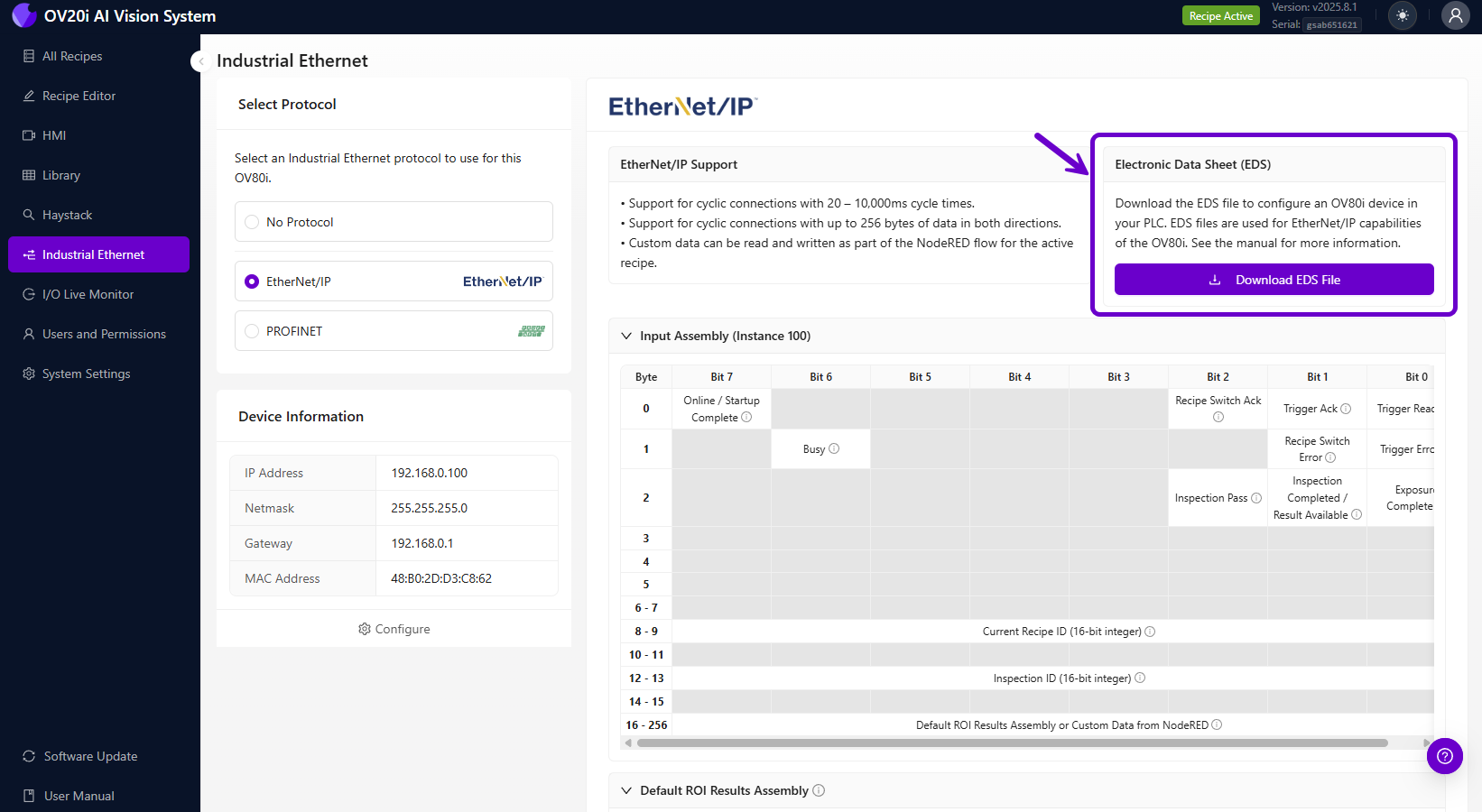
- Download the EDS file from either:
- The camera's web interface (Industrial Ethernet > EtherNet/IP page)
- Or directly here: OV20i EDS File
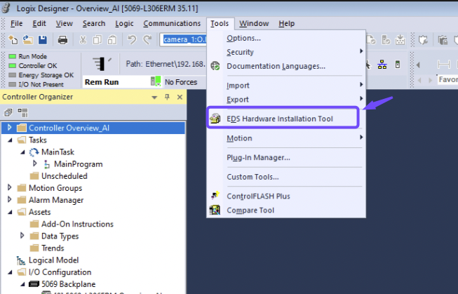
- In Studio 5000, go to Tools > EDS Hardware Installation Tool
- Select Register an EDS file, then Browse and select the OV20i EDS file
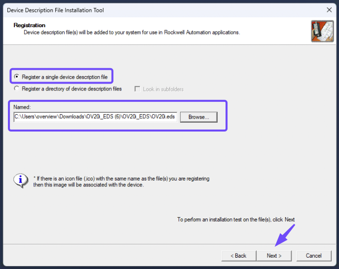
- Follow the installation wizard to complete EDS registration
You cannot add the OV20i module in Studio 5000 without the EDS file installed. The device will not appear in the "Select Module Type" dialog. If you skip this step, your only option is a Generic Ethernet Module, which requires manually entering assembly instances and data sizes.
Step 2: Configure OV20i for EtherNet/IP
2.1 Access Industrial Ethernet Settings
- Open the OV20i web interface
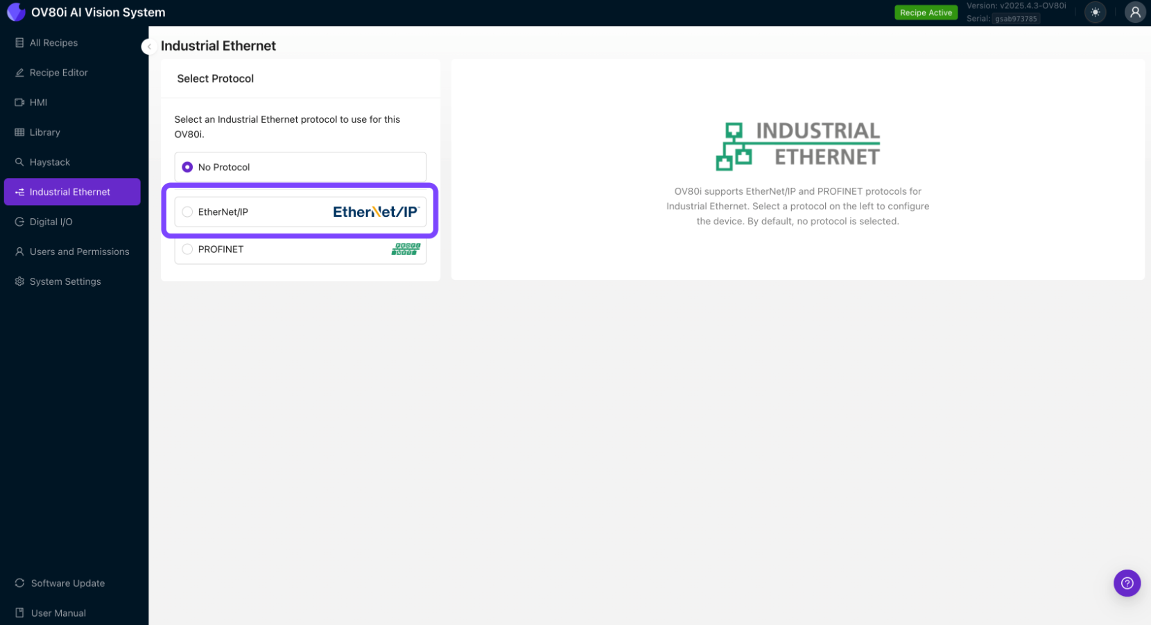
- Navigate to "Industrial Ethernet" in the left menu
- You'll see the Industrial Ethernet configuration page
2.2 Enable EtherNet/IP Protocol
- In the Industrial Ethernet menu, select "EtherNet/IP" protocol
- Click "Enable" to activate EtherNet/IP communication
- Note your camera's network settings in the Device Information window
2.3 Configure Network Settings
- Set Static IP Address (recommended for production)
- Go to System Settings > Network
- Configure static IP in same subnet as your PLC
- Example: Camera:
192.168.1.100, PLC:192.168.1.50
- Configure Subnet Mask (typically
255.255.255.0) - Set Gateway if required for your network
2.4 Configure EtherNet/IP Device Settings
- Device Name: Set a meaningful name for your camera
- Assembly Configuration: Configure input/output data structures
- Connection Parameters: Set appropriate timeout and RPI (Requested Packet Interval) values
- Click "Save" to apply EtherNet/IP settings
Step 3: Configure PLC Recipe Settings
3.1 Enable PLC Triggering (Optional)
- Navigate to Recipe Editor > Imaging Setup
- Set Trigger Mode to "PLC Trigger"
- Important: Once PLC Trigger is enabled, manual triggering is disabled
3.2 Configure Pass/Fail Output
- Navigate to Recipe Editor > IO Block
- Ensure your inspection logic ends with "Final Pass/Fail" node
- This sets the Inspection Pass bit in the EtherNet/IP assembly
Step 4: Add OV20i Module in Studio 5000
4.1 Add OV20i Module to PLC Project
- In Studio 5000, open your PLC project
- Go to I/O Configuration in the project tree
- Right-click on Ethernet module and select "New Module"
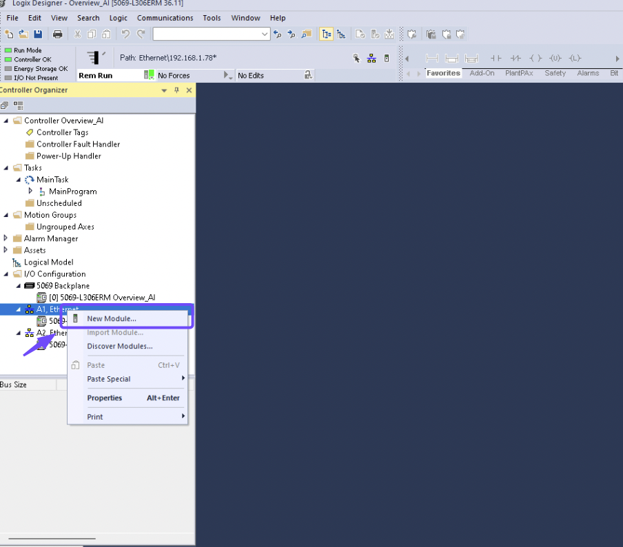
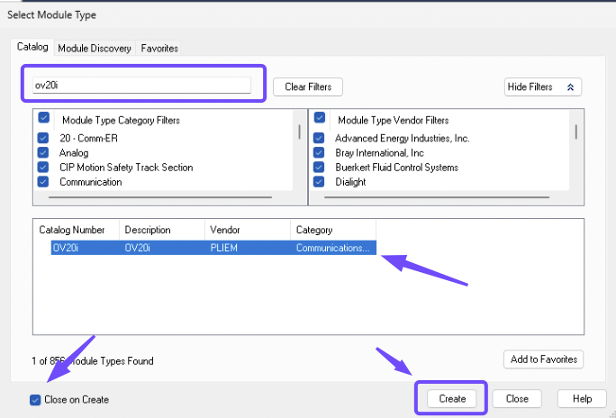
- Search for "OV20i" or "Overview" in the module catalog (the OV20i appears here because you installed the EDS file in Step 1)
- Select the OV20i module and click "Create"
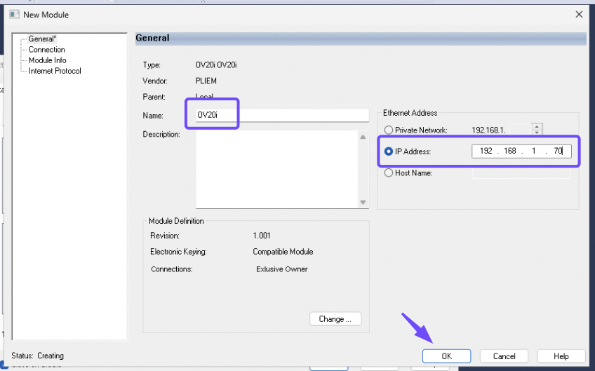
4.2 Configure Module Properties
- Name: Enter descriptive name for the camera
- IP Address: Enter the OV20i's IP address (e.g.,
192.168.1.100) - RPI (Requested Packet Interval): Set to 100ms or as required
- Connection Parameters: Configure input/output data sizes
- Click "OK" to create the module
4.3 Map I/O Data
- Input Data: Inspection results, status bits, camera ready signals
- Output Data: Trigger commands, recipe change requests, control signals
- Create tags in your PLC program to map to the I/O data
- Example Input Tags:
Camera_InspectionPass: BOOLCamera_Ready: BOOLCamera_Busy: BOOL
- Example Output Tags:
Camera_Trigger: BOOLCamera_RecipeSelect: INT
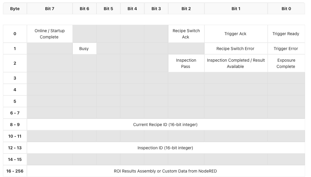
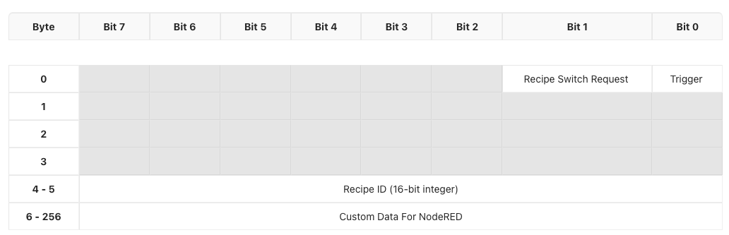
Input Assembly (OV20i → PLC)
Output Assembly (PLC → OV20i)
Step 5: Test EtherNet/IP Communication
5.1 Verify Connection Status
- In Studio 5000, check module status in I/O Configuration
- Green checkmark indicates successful connection
- Red X indicates communication issues
5.2 Test Basic Communication
- Monitor input data from camera in PLC program
- Toggle output signals to camera and verify response
- Check diagnostic information for any error codes
5.3 Test Trigger and Response
- Enable PLC trigger output to camera
- Monitor inspection results in PLC input data
- Verify pass/fail status updates correctly
- Check timing of trigger and response cycles
Part 2: PROFINET Connection
Step 1: Download and Install the GSDML File
The GSDML (General Station Description Markup Language) file must be installed in TIA Portal before you can add the OV20i to your hardware configuration. Without it, the camera will not appear in the hardware catalog.
- Download the GSDML file from either:
- The camera's web interface (Industrial Ethernet > PROFINET page)
- Or directly here: OV20i GSDML File
- In TIA Portal, go to Options > Manage general station description files (GSD)
- Browse to the folder where you saved the GSDML file, select it, and click Install
- Once installed, close the dialog. The OV20i will now appear in the hardware catalog.
You cannot add the OV20i device in TIA Portal without the GSDML file installed. The device will not appear under Other field devices > PROFINET IO in the hardware catalog. Always install the GSDML file first.
Step 2: Configure OV20i for PROFINET
2.1 Access Industrial Ethernet Settings
- Open the OV20i web interface
- Navigate to "Industrial Ethernet" in the left menu
- Select "PROFINET" protocol from the options
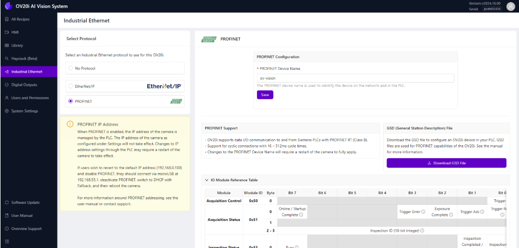
2.2 Enable PROFINET Protocol
- Click "Enable PROFINET" to activate protocol
- Note: PROFINET manages camera IP address when enabled
- Camera IP settings may be overridden by PLC configuration
2.3 Configure PROFINET Device Settings
- PROFINET Device Name: Set unique name for camera
- Example: "OV20i_Line1_Station2"
- Must be unique if multiple cameras on same PLC
- Device Configuration: Note the device capabilities and data structure
- Click "Save" to apply PROFINET settings
Step 3: Configure PLC Recipe Settings
3.1 Enable PLC Triggering (Optional)
- Navigate to Recipe Editor > Imaging Setup
- Set Trigger Mode to "PLC Trigger" if needed
- Warning: Manual triggering disabled when PLC trigger is active
3.2 Configure Pass/Fail Logic
- Navigate to Recipe Editor > IO Block
- Ensure inspection logic concludes with "Final Pass/Fail" node
- This sets the Inspection Pass bit in PROFINET input assembly
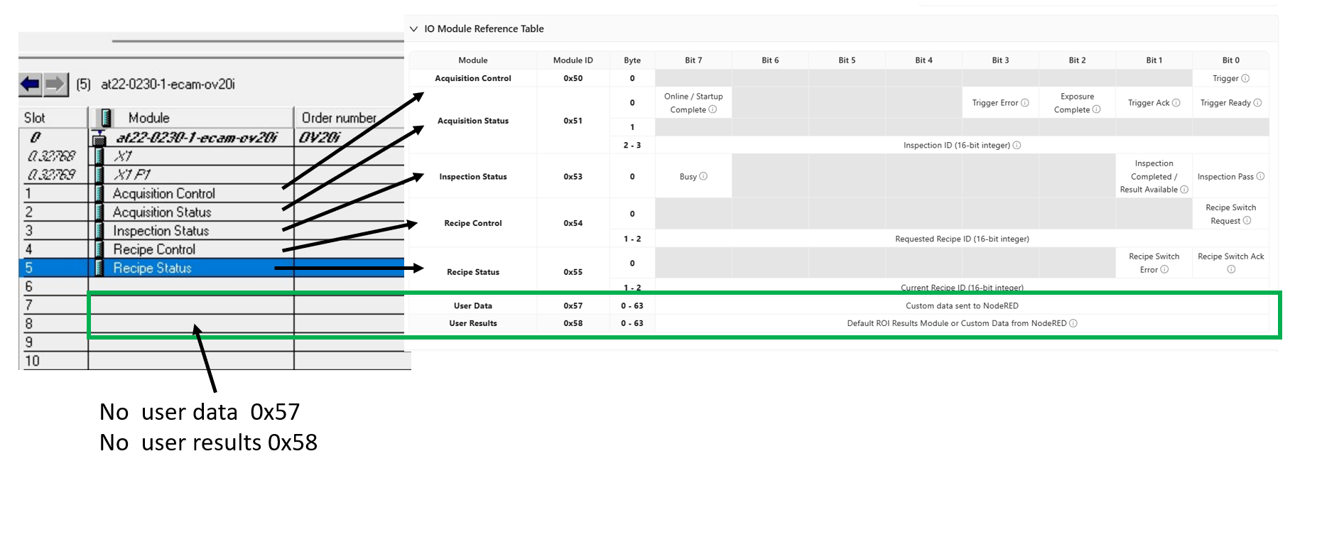
Step 4: Add OV20i in TIA Portal
If you want to receive data back from Node-RED to Profinet PLC, make sure to add the custom data modules (User Data - 64 bytes and User Results - 64 bytes).
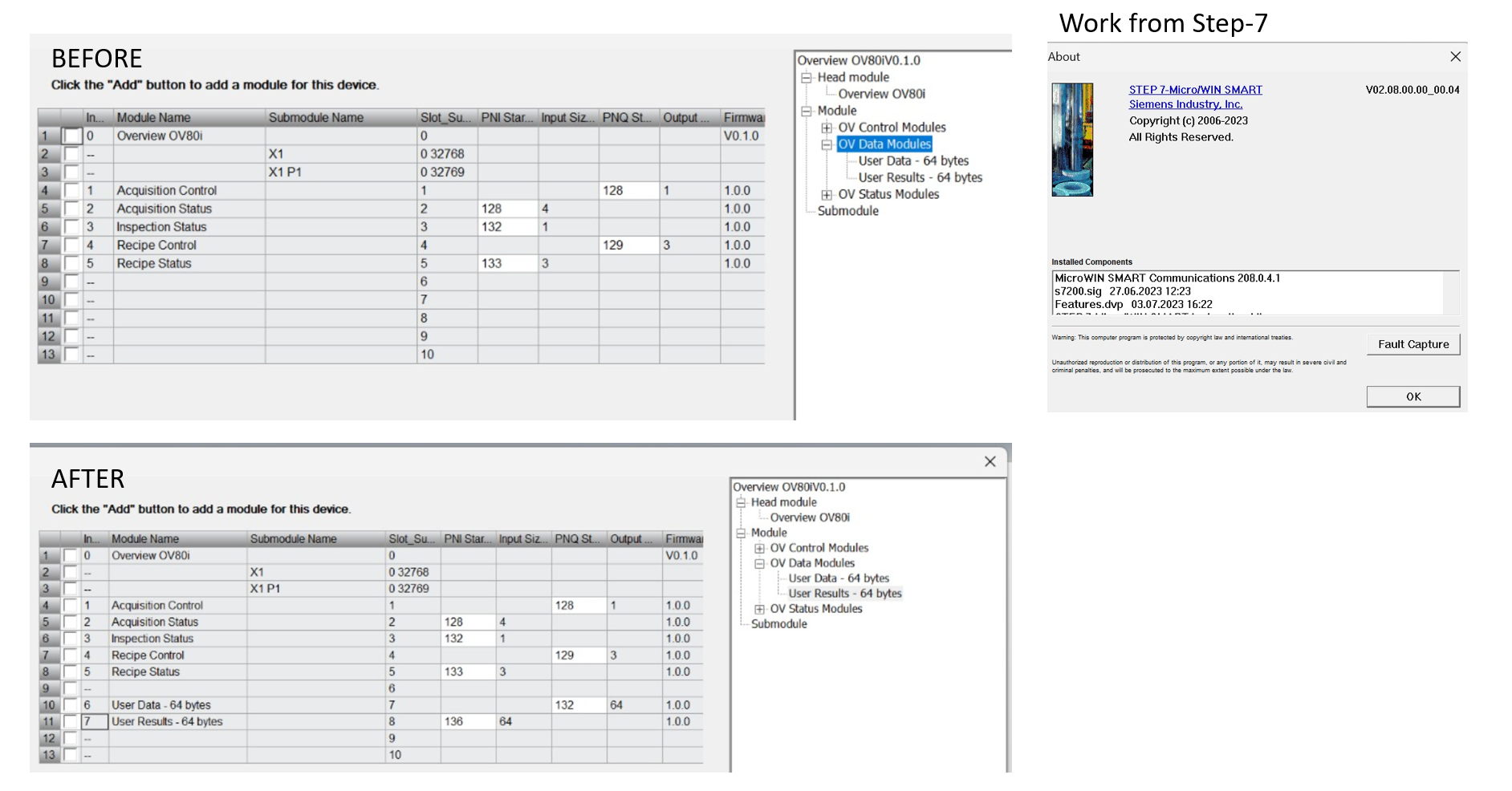
4.1 Add OV20i to Hardware Configuration
- In TIA Portal, open Device & Networks view
- From the Hardware catalog, expand Other field devices > PROFINET IO
- Locate OV20i device and drag it to the network view
- Connect the OV20i to your PLC's PROFINET interface
4.2 Configure Device Properties
- Device Name: Set same name as configured in camera
- IP Address: Configure IP address (may be managed by PLC)
- Update Time: Set cycle time (default 128ms recommended)
- I/O Data: Configure input/output data modules as needed
4.3 Assign IP Address and Device Name
- Compile hardware configuration
- Go online with PLC
- Assign IP address to OV20i device
- Assign device name matching camera configuration
Step 5: Test PROFINET Communication
5.1 Verify Device Status
- In TIA Portal, check device status in Device & Networks
- Green status indicates successful communication
- Red status indicates communication problems
5.2 Test Data Exchange
- Monitor input data from camera in PLC program
- Control output data to camera and verify response
- Check diagnostic buffers for any error messages
5.3 Test Inspection Cycle
- Activate PLC trigger to camera
- Monitor inspection results in PLC input data
- Verify pass/fail status transmission
- Check cycle timing meets application requirements
Step 5: Troubleshooting PLC Communication
5.1 Common EtherNet/IP Issues
| Problem | Symptoms | Solution |
|---|---|---|
| Connection timeout | Module shows red X in Studio 5000 | Check IP addresses, network connectivity, firewall settings |
| Data not updating | I/O data remains static | Verify EDS file version, check assembly configuration |
| Trigger not working | Camera doesn't respond to PLC trigger | Check trigger bit mapping, verify PLC output is active |
| Slow response | Delayed inspection results | Adjust RPI timing, check network load |
5.2 Common PROFINET Issues
| Problem | Symptoms | Solution |
|---|---|---|
| Device not found | Camera not visible in TIA Portal | Check GSDML file installation, verify device name |
| IP address conflicts | Communication errors | Ensure unique IP addresses, check subnet configuration |
| Cycle time errors | Watchdog timeouts | Increase cycle time, check network performance |
| Data format errors | Incorrect I/O data | Verify GSDML version, check data structure mapping |
5.3 Network Diagnostics
- Ping test between camera and PLC
- Check network switches and cable integrity
- Monitor network traffic for bandwidth issues
- Verify firewall settings don't block communication
Step 6: Performance Optimization
6.1 Timing Considerations
- EtherNet/IP RPI: Start with 100ms, adjust based on application needs
- PROFINET Cycle Time: Use 128ms default, reduce only if required
- Inspection Time: Consider total inspection time in cycle planning
- Network Latency: Account for network delays in timing calculations
6.2 Data Efficiency
- Minimize data size in I/O assemblies
- Use appropriate data types (BOOL vs INT vs REAL)
- Avoid unnecessary data in cyclic communication
- Use explicit messaging for non-critical data
6.3 Network Management
- Use managed switches for better diagnostics
- Implement redundancy for critical applications
- Monitor network utilization to prevent congestion
- Plan IP address ranges for scalability
Success! Your PLC Communication is Established
Your OV20i camera can now:
✅ Communicate with PLCs using industrial protocols
✅ Receive trigger signals from automation systems
✅ Send inspection results to PLC control logic
✅ Integrate seamlessly with production line automation
✅ Support remote recipe changes and system coordination
Best Practices
Production Deployment
- Use static IP addresses for consistent communication
- Document all network settings and device configurations
- Test thoroughly before production deployment
- Plan for maintenance and troubleshooting procedures
Security Considerations
- Segment industrial networks from office networks
- Use managed switches with appropriate security features
- Monitor network access and device communications
- Keep firmware updated on all network devices
Maintenance
- Regular network health checks and diagnostics
- Monitor communication statistics for performance trends
- Update device drivers and configuration files as needed
- Maintain documentation of all network configurations
Next Steps
After establishing PLC communication:
- Trigger Inspections from PLC — Set up PLC-triggered inspections using EtherNet/IP or PROFINET
- Change Recipes from PLC — Switch camera recipes remotely via PLC commands
- PLC Communication Details (EtherNet/IP) — Detailed data mapping, assembly layouts, and timing
- Develop PLC control logic for your specific application
- Create operator interfaces for monitoring and control
📥 Download Files
Download these essential files for PLC integration:
EtherNet/IP Configuration
- OV20i EDS File - Electronic Data Sheet for Allen-Bradley Studio 5000
- Required for configuring OV20i module in ControlLogix/CompactLogix systems
PROFINET Configuration
- OV20i GSDML File - Device description for Siemens TIA Portal
- Required for configuring OV20i device in PROFINET networks
Sample PLC Code
-
Recipe Switch Routine - Ladder logic for recipe switching
- Complete Allen-Bradley routine for changing camera recipes via PLC
-
Camera Trigger Routine - Ladder logic for triggering inspections
- Complete Allen-Bradley routine for triggering camera and handling results
File Usage Notes:
- EDS Files: Import into Studio 5000 via Tools → EDS Hardware Installation Tool
- GSDML Files: Import into TIA Portal via Options → Manage GSD Files
- L5X Files: Import ladder logic directly into your Allen-Bradley project