AI-POWERED DOCS
What do you want to know?
OV20i Technical Specifications
This page provides comprehensive technical specifications for the OV20i smart camera, including hardware capabilities, performance parameters, pinouts, and environmental requirements.
System Overview
Model: OV20i Industrial AI Vision Camera
Application: Advanced machine vision with integrated AI capabilities
Physical Specifications
| Parameter | Specification | Notes |
|---|---|---|
| Height | 123 mm (4.85") | |
| Width | 82 mm (3.25") | |
| Depth | 63 mm (2.5") | |
| Weight | 700 g (~1.5 lbs.) | |
| Mounting | 4x M4 (front or rear) | See mounting documentation |
| Enclosure Rating | IP54 | Dust and moisture protection |
| Certifications | CE/FCC | Industrial compliance |
Power Specifications
| Parameter | Specification | Notes |
|---|---|---|
| Input Voltage | 19-24 VDC | Industrial standard |
| Maximum Power | 18W | Peak consumption |
| Typical Power | 15W | Normal operation |
| Current Draw | ~1A @ 24V | Approximate |
Environmental Specifications
| Parameter | Specification | Notes |
|---|---|---|
| Operating Temperature | 0-45°C | Industrial environment |
| Storage Temperature | -20 to +70°C | Non-operating |
| Humidity | 10-90% RH | Non-condensing |
| Vibration Resistance | Industrial grade | Suitable for production lines |
Image Sensor Specifications
| Parameter | Specification | Notes |
|---|---|---|
| Sensor Model | Sony IMX296 | Industrial grade |
| Resolution | 1.6 MP | 1408 x 1080 pixels |
| Frame Rate | 60 fps | Maximum |
| Sensor Size | 1/2.9" | |
| Shutter Type | Global Shutter | Motion immunity |
| Color/Mono | Color | RGB color sensor |
| Pixel Size | 3.45 μm x 3.45 μm |
Processor System Specifications
NVIDIA Xavier NX Computing Module
| Component | Specification | Details |
|---|---|---|
| CPU | 6-core NVIDIA Carmel ARM® v8.2 64-bit | Max frequency: 1.9GHz |
| Cache | 6MB L2 + 4MB L3 | |
| GPU | 384-core NVIDIA Volta GPU | |
| AI Acceleration | 48 Tensor Cores | Deep learning optimization |
| Memory | 8 GB 128-bit LPDDR4 | System memory |
| Storage | 16 GB eMMC | Internal storage |
Optical System Specifications
Lens System
| Parameter | Specification | Notes |
|---|---|---|
| Mount Type | S-Mount (M12) | Standard threading |
| Standard Lens | 12mm variable focal length | Factory default |
| Available Options | 6mm, 8mm, 16mm, 25mm | Optional lenses |
| Focus Type | Motorized variable focus | Programmable |
| Aperture | Auto/Manual | Software controlled |
Illumination System
| Parameter | Specification | Notes |
|---|---|---|
| LED Count | 8 x PWM white LEDs | Programmable intensity |
| Control Method | PWM (Pulse Width Modulation) | Precise control |
| LED Type | White LED | Color-neutral illumination |
| Power Management | Integrated thermal control | Heat management |
Connectivity Specifications
External Ports
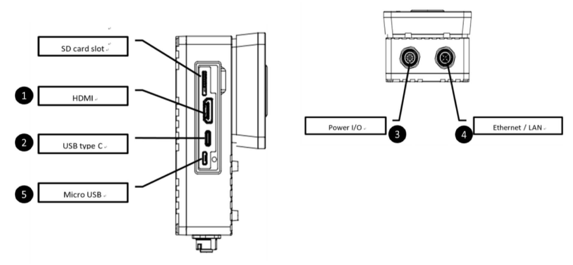
| Port # | Type | Connector | Description |
|---|---|---|---|
| 1 | HDMI | HDMI 2.0 | Not used in OV20i |
| 2 | USB Type-C | USB 3.0 | Optional ethernet dongle |
| 3 | Power I/O | M12 A-Coded 17 Pin | Power, Digital I/O, RS485 |
| 4 | Ethernet | M12 X-Coded | Network, PLC communication |
| 5 | Micro USB | Micro USB | Emergency programming access |
Network Specifications
| Parameter | Specification | Notes |
|---|---|---|
| Ethernet | 10/100/1000 Base-T | Gigabit capable |
| Protocols | Ethernet/IP, Profinet | Industrial protocols |
| Default IP | 192.168.0.100 | Static default |
| Emergency IP | 192.168.55.1 | Micro-USB access |
| DHCP Support | Yes | Configurable |
Digital I/O Specifications
| Signal | Pin | Count | Type | Specifications |
|---|---|---|---|---|
| Trigger Input | 16 | 1 | Digital Input | NPN Active Low - Pull to GND to activate |
| Digital Input 0 | 8 | 1 | Digital Input | NPN Active Low - Pull to GND to activate |
| Digital Input 1 | 9 | 1 | Digital Input | NPN Active Low - Pull to GND to activate |
| Digital Output 0 | 10 | 1 | Digital Output | NPN Sinking - Max 100mA, sinks to GND when active |
| Digital Output 1 | 11 | 1 | Digital Output | NPN Sinking - Max 100mA, sinks to GND when active |
| Reset | 15 | 1 | System Control | NPN Active Low - Pull to GND to reboot |
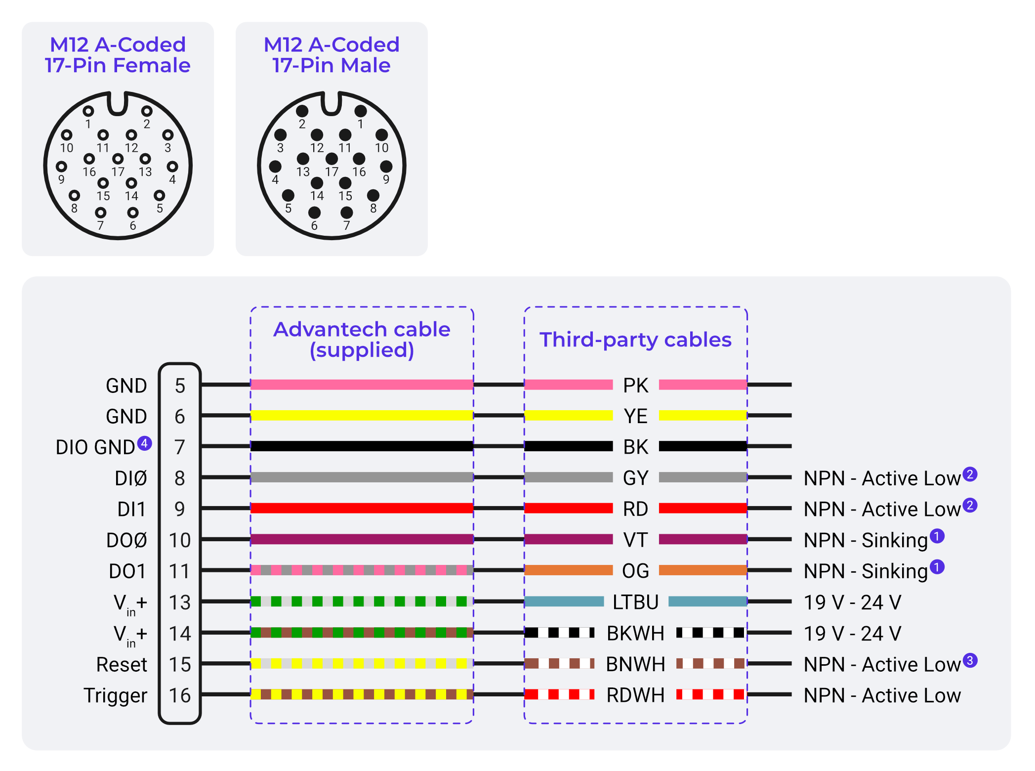
Legacy cable image: this diagram shows the original flying-leads colors used by the 3M & 5M cables. If your cable matches these colors, wire directly from it. If it does not match (10M cable, solid colors plus a Yellow/Green lead on pin 12), see the Wire Color Reference for the 3M & 5M vs 10M cable colors.
I/O Electrical Characteristics
| Parameter | Specification | Notes |
|---|---|---|
| Input Voltage Range | 0-24 VDC | |
| Input Logic | Pull to GND = Active | NPN compatible |
| Output Current | 100 mA maximum | Per output |
| Output Logic | Sinking to GND | When active |
| Output State | Floating | When inactive |
- Digital outputs (DO0 / DO1) are NPN open-collector, sinking only. They pull the line to GND when active and cannot source +24 V. An external pull-up or load to +24 V must be provided for proper operation.
- DIO GND (Pin 7) must be connected to GND for digital input functionality to work
- DIO GND is tied to GND through a thermal fuse
- When connecting to systems with different power supplies, use DIO GND to tie grounds together
- Reset (Pin 15) - Pull to GND to reboot camera (not needed for most applications, keep floating to avoid unexpected restarts)
M12 A-Coded 17 Pin Connector Pinout
Pin Assignment Table
The wire colors of the flying-leads Power & I/O cable depend on the cable length. The 3M and 5M cables use striped secondary colors, while the 10M cable uses solid colors and includes an extra lead on pin 12. Identify your cable by its length before wiring.
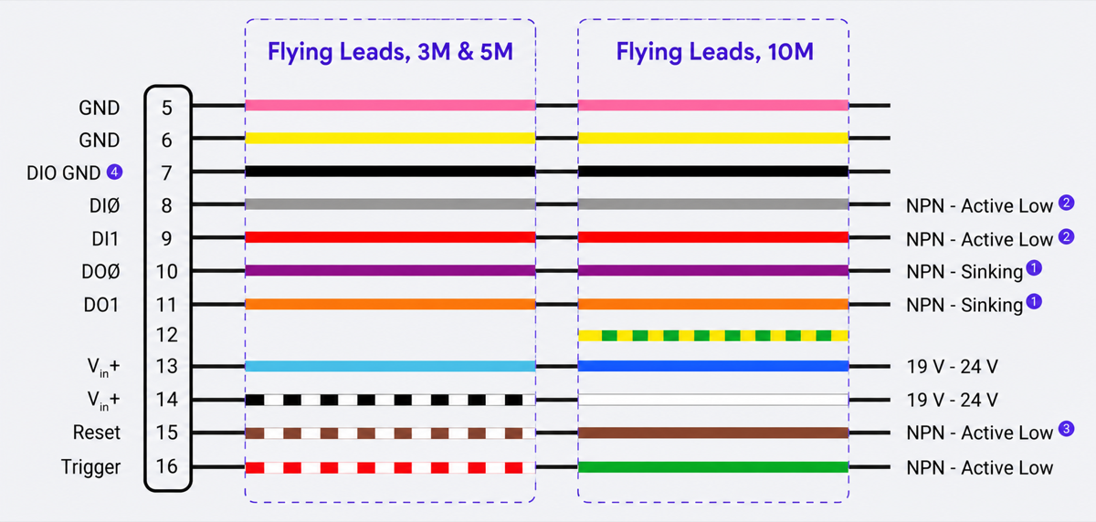
| Pin | Signal | Wire Color (3M & 5M Cable) | Wire Color (10M Cable) | Function |
|---|---|---|---|---|
| 5 | GND | Pink (PK) | Pink (PK) | Power Ground |
| 6 | GND | Yellow (YE) | Yellow (YE) | Power Ground |
| 7 | DIO GND | Black (BK) | Black (BK) | Digital I/O Ground |
| 8 | DI0 | Gray (GY) | Gray (GY) | Digital Input 0 - NPN Active Low |
| 9 | DI1 | Red (RD) | Red (RD) | Digital Input 1 - NPN Active Low |
| 10 | DO0 | Violet (VT) | Violet (VT) | Digital Output 0 - NPN Sinking |
| 11 | DO1 | Orange (OG) | Orange (OG) | Digital Output 1 - NPN Sinking |
| 12 | Reserved | No lead | Yellow/Green (YEGN) | Not connected internally |
| 13 | Vin+ | Light Blue (LTBU) | Blue (BU) | Power Input Positive (19-24V) |
| 14 | Vin+ | Black/White (BKWH) | White (WH) | Power Input Positive (19-24V) |
| 15 | Reset | Brown/White (BNWH) | Brown (BN) | System Reset - NPN Active Low |
| 16 | Trigger | Red/White (RDWH) | Green (GN) | Trigger Input - NPN Active Low |
| 1,2,3,4,17 | Reserved | - | - | Not connected |
On the 10M cable, the Yellow/Green lead on pin 12 is not a protective earth conductor, and the solid Green lead on pin 16 is the Trigger input. Do not wire by color convention alone. Leave the pin 12 lead unconnected.
Power Connections
Dual Power Input Design:
- Pins 13 and 14 are both Vin+ (19-24V positive) inside the camera
- Pins 5 and 6 are both power GND
- Because each pair is internally common, connecting one pin of each pair is enough to run the camera
- Wiring both pairs doubles the conductor cross-section, which reduces voltage drop on long cable runs
If the camera will not boot or browns out under load, connect the 24V supply to both Vin+ pins (13 and 14) and both grounds (5 and 6) rather than a single terminal each. The two ground wires can share the same terminal on your supply or terminal block.
Image Signal Processing
| Feature | Capability | Notes |
|---|---|---|
| Color Debayering | Hardware accelerated | Real-time processing |
| Sharpness Control | Adjustable | Software configurable |
| White Balance | Auto/Manual | CCM correction |
| Noise Reduction | Dark noise correction | Low-light performance |
| Brightness Control | Software adjustable | Exposure compensation |
| Lens Distortion Correction | Software-based | Focal length specific |
AI Processing Specifications
| Parameter | Specification | Notes |
|---|---|---|
| AI Framework | NVIDIA DeepStream SDK | Optimized for Xavier NX |
| Model Types | Classification, Segmentation | AI-based inspection |
| Training Modes | Fast, Accurate/Production | Classification only |
| Inference Speed | Real-time | 60 fps capable |
| Model Storage | Local on-device | 16 GB eMMC |
Synchronization & Triggering
| Mode | Type | Description |
|---|---|---|
| Hardware Trigger | Digital Input | External signal triggering |
| Software Trigger | Network/Manual | PLC or manual triggering |
| Aligner Trigger | Software | Template-based triggering |
| Interval Trigger | Timer-based | Periodic triggering |
Performance Specifications
| Parameter | Specification | Notes |
|---|---|---|
| Processing Speed | Real-time @ 60 fps | Depends on AI model complexity |
| Latency | < 100ms | Typical trigger to result |
| Accuracy | Model dependent | Based on training quality |
| Throughput | Up to 3600 inspections/minute | At 60 fps |
Standard Package Contents
| Item | Quantity | Description |
|---|---|---|
| OV20i Camera | 1 | Main camera unit |
| Mounting Plate | 1 | Hardware included |
| I/O Power Cable | 1 | M12 connector with terminal block |
| Ethernet Cable | 1 | M12 to RJ45 |
| Documentation | 1 set | Quick start guide |
Compliance & Standards
| Standard | Compliance | Description |
|---|---|---|
| CE Marking | Yes | European conformity |
| FCC | Yes | US electromagnetic compatibility |
| IP Rating | IP54 | Dust and water protection |
| IEC 704-1:1982 | Yes | Sound pressure ≤ 70 dB(A) |
| Industrial Standards | Multiple | Ethernet/IP, Profinet |
🔗 See Also
Technical Support
For technical assistance:
- Overview Support: support@overview.ai
- Documentation: Available in this manual
Specifications subject to change without notice. For the most current specifications, consult the latest documentation.