AI-POWERED DOCS
What do you want to know?
Step 2: Alignment
The aligner is the most powerful (and the most misunderstood) part of the camera. Once you understand it, everything clicks. Let's explain it simply.
See it in action
Play with the simulator before you read on. Toggle the aligner off, then move the sliders to shift and rotate the part. The orange ROI shows the region of interest (ROI) tracking the part, and the green boxes turn red when the aligner can no longer follow.
Camera Settings
Simulate Real World
Move the part coming down the line.
Legend
What alignment does (and why you need it)
Imagine you're inspecting screws on a circuit board. You've drawn a little box around each screw location. But what happens when the next board comes in slightly shifted to the left? Or rotated a degree? Your boxes are now looking at the wrong spots.
The aligner solves this. It looks at each new image, figures out where the part moved to, and shifts all your inspection boxes to match. It's like having a helper who says "the board moved 3 pixels left and rotated 0.5 degrees, so let me move all your boxes to match."
Why this is powerful: When your inspection boxes can move with the part, you can make them smaller. And smaller boxes need less data to train the AI. It's a cascading benefit that starts with good alignment.
Why alignment is the foundation of everything
The aligner isn't just a nice-to-have. It's the first domino in a chain that determines the accuracy of your entire inspection. Here's the pipeline:
Alignment → Smaller ROIs → Less training data needed → More accurate AI
Each step depends on the one before it:
- Good alignment means your inspection boxes track the part precisely, even when it shifts or rotates on the conveyor.
- Precise tracking means you can draw smaller inspection boxes (ROIs). You don't need to add extra padding to account for part movement.
- Smaller ROIs mean the AI sees a tightly cropped view of just the feature you care about (a screw, a connector, a weld), not a sea of irrelevant background.
- Less background noise means the AI needs fewer training images to learn, and it makes fewer mistakes in production.
The aligner doesn't inspect anything. It doesn't judge pass or fail. Its only job is to dynamically move your inspection boxes so they land on the right spots every time. The inspection boxes do the actual inspecting. The AI inside those boxes does the actual judging. But none of that works if the boxes are in the wrong place.
Think of it as a chain: Aligner → ROIs → Classifier/Segmenter. If the first link is weak, everything downstream breaks.
How it works: think of it like a puzzle
The aligner works by matching edges. Here's a simple way to think about it:
- You take a "reference photo" (the template image) of a perfect part
- You point to specific features on that photo (corners, edges, holes) that look the same on every part
- Every time a new part arrives, the camera finds those same features in the new image
- It calculates the difference: "this part is 5 pixels left, 2 pixels up, and tilted 1.2 degrees"
- It moves all your inspection boxes by exactly that amount
It's like playing a matching game. The camera finds the features you showed it and uses them as anchor points.
The golden rule of alignment
This single rule will determine whether your alignment works perfectly or jitters frustratingly. Here's why:
Think of it like this: Imagine you're trying to figure out if a picture frame on the wall is crooked.
- If you only look at one corner, you might think it's straight when it's actually tilted
- If you look at two opposite corners (top-left and bottom-right), you can instantly tell if it's crooked, and by exactly how much
The same principle applies to the aligner. With one region on one side of the part, a tiny measurement error of 0.5 degrees stays at 0.5 degrees. But with two regions on opposite sides, that same error averages out to about 0.05 degrees, ten times more accurate.
Critical: what NOT to align to
This is the number one cause of alignment failures. Before you touch the aligner interface, internalize these two rules.
1. Never align to defects
Defects are unpredictable. A scratch, a dent, or a missing screw might look completely different on every part, or it might not be there at all.
If you tell the camera to use a scratch as its anchor point, the alignment will completely fail when a perfectly good, scratch-free part comes down the line. The camera won't know where to place your inspection boxes, and the system will break down.
Use the aligner to find the part using features that are always there (rigid edges, machined corners, drilled holes). Then use the inspection boxes to look for the unpredictable defects. The aligner finds the part. The inspection boxes find the problems.
2. Never align to moving parts or labels
If you align to something that can move independently of the main object, like a loose wire, a cardboard flap, or a barcode sticker, you will accidentally trick the camera into shifting all your inspection boxes to the wrong position.
Example: Imagine you anchor your aligner to a barcode sticker. On the next part, a worker accidentally places that sticker a half-inch to the left. The camera sees the sticker move and assumes the entire part shifted a half-inch to the left. It shifts all of your inspection boxes to compensate. But the actual metal part didn't move, only the sticker did. Now all of your inspection boxes are looking at the wrong spots, causing false failures across the board.
Only anchor to features that are permanently fixed to the rigid body of the part: machined edges, molded corners, drilled holes, PCB outlines. Never anchor to labels, stickers, wires, flaps, or anything a human could accidentally reposition.
Quick summary: what to align to vs. what to avoid
| Align to (permanent, rigid features) | Never align to (variable or movable) |
|---|---|
| Machined edges | Scratches, dents, or defects |
| Drilled holes | Barcode stickers or labels |
| PCB outlines | Loose wires or cables |
| Molded corners or features | Cardboard flaps or packaging |
| Stamped metal edges | Tape, adhesive, or markers |
| Cast or forged geometry | Any feature a human could reposition |
Setting up the aligner
The OV20i web interface was redesigned in v2026.5. Check your software version in the top-right corner of the camera UI and pick the matching tab. Your choice carries across every page in this setup flow.
- Older versions
- v2026.5 and newer
Here's what the aligner setup screen looks like. You'll see your template image with colored edge highlights showing what the aligner is using as reference features:
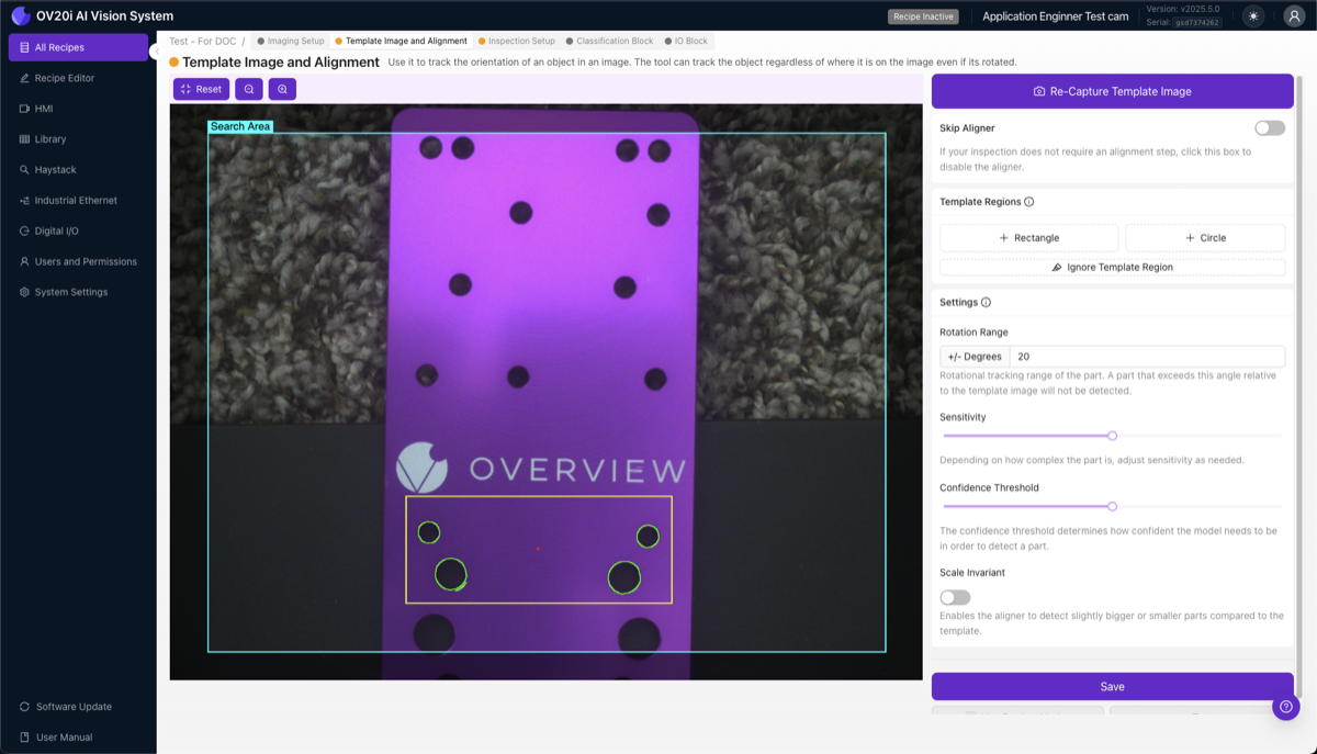
1. Capture the template image. Place a good, defect-free part in the camera's field of view. This becomes the reference every future part is compared against. Keep it well-lit with clear edges, clean, and positioned the way it will appear in production. Click Capture Template Image.
2. Add template regions. Click + Rectangle (or + Circle) to create a template region, and place 2-3 of them. Anchor to features that never change, such as machined edges, drilled holes, PCB outlines, molded features, and stamped corners. Avoid textured or variable surfaces, areas where defects appear, reflective glare, tiny details, and labels or markings that could move.
3. Understand the edge highlights. When you place a region, you'll see colored highlights:
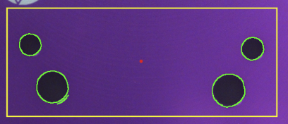
- Green highlights = strong, usable edges detected. This is what you want.
- Red highlights = not enough edges. Move the region to a feature with clearer edges.
- Red dot = the alignment reference point (center of all your regions of interest (ROIs)).
4. Clean up noisy edges with the Ignore tool. This step is overlooked by most people, and it makes a huge difference. Click Ignore Template Region and paint over any edges you don't want the aligner to use: random background texture, glare or reflections, surface noise, edges from debris or labels, and anything that might change between parts.
5. Adjust sensitivity.

The sensitivity slider controls how aggressively the aligner detects edges inside your template regions. Set it to the lowest value that gives solid green highlights across your regions. Too low and regions stay red (not enough features to match reliably); too high and green spreads onto background texture, so the aligner can lock onto noise and jitter.
If you need more edges, increase the sensitivity slider. But the more you increase sensitivity, the more important it is to go back and paint out the new noise with the Ignore tool. Cast a wide net, then carefully pick out only the good fish.
6. Set rotation range.
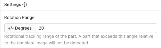
Controls how much rotation the aligner searches for: ±180° finds the part at any rotation (best for most applications), ±5-20° matches only near the expected orientation, ±0° is an exact angle match.
If you set a narrow range like ±5° and a part comes in rotated 10°, the aligner won't match it, and you can use this failure as a reject signal. Handy for catching parts that aren't properly oriented.
7. Set confidence threshold.

How confident the aligner needs to be that it found the right match. Range 0.0 to 1.0, recommended 0.6 to 0.9. Too high and it may miss valid parts; too low and it may match the wrong features.
8. Enable Scale Invariant (if needed). If your part can be ±10% closer or farther from the camera (height variation on a conveyor, for example), enable this. Otherwise, leave it off for maximum speed.
9. Save and test. This is the most important step, so do not skip testing. Click Save to train and deploy the aligner, then click Live Preview Mode and move the part around: left, right, up, down; rotate it within your expected range; put it in the corners of the frame; try different valid parts. Try to break it. If alignment doesn't track reliably, fix it now. If you move on to ROIs and training and discover it later, you'll have to redo everything. That's the waterfall.
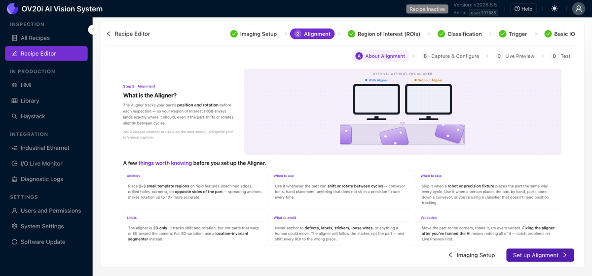
In the recipe editor, open Step 2: Alignment. It is split into four sub-tabs across the top: About Alignment, Capture & Configure, Live Preview, and Test. The Quick guide button runs a short guided tour of the page.
About Alignment
Start here for a refresher. This tab shows a "with versus without aligner" illustration and quick-reference columns covering what to anchor to, when to use the aligner, when to skip it, the aligner's limits, and what to avoid.
Capture & Configure
This is the main setup tab, a guided checklist you work down from top to bottom.
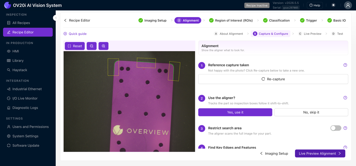
1. Reference capture taken. The tab opens on the reference image you captured. If you are not happy with it, click Re-capture to take a new one. Click What makes a good reference photo? for the full checklist:
- Show the whole part, filling about 60 to 80% of the frame.
- Use even lighting, with no harsh shadows or glare.
- Place the part exactly as it appears in production.
- Keep everything still while the reference is captured.
- Use a clean, plain background.
2. Use the aligner?
- Yes, use it tracks the part shift to shift, so your inspection boxes follow it.
- No, skip it when your parts are held in a precision fixture and never move.
3. Restrict search area. By default the aligner scans the full image for your part. Turn this switch on to limit the search to a region of the image, a useful speed-up when the part always appears in roughly the same place.
4. Find Key Edges and Features. Click + Rectangle and drag on the image to draw a template region. Place 2 or 3 of them, anchored to features that are always present such as logos, holes, and sharp corners, spread as far apart as possible on opposite sides of the part. Click a region to select it, then use the delete button that appears to remove it.
When you place a region, the aligner highlights the edges it found inside it and marks the alignment reference point with a red dot:
- Green highlights are strong, usable edges. This is what you want.
- Red highlights mean not enough edges were found. Move the region to a feature with clearer edges.
- The red dot is the alignment reference point, the center of all your regions.
5. Clean up extra edges. Use Draw mask to paint over edges you do not want the aligner to use, such as background texture, glare, debris, or anything that changes between parts, and Erase mask to undo. Adjust the Pen size slider for finer work, or Clear all masks to start over. Cleaner edges dramatically raise the chance of a reliable match.
6. Settings. Fine-tune how strict the aligner is.
Rotation Range sets how many degrees of rotation the aligner searches, up to plus or minus 180° (a full 360° sweep). Narrow it to use misorientation as a reject signal.
Sensitivity controls how many edges are found and matched. Use the lowest setting that still gives solid green on your features.
Confidence Threshold rejects any alignment less confident than the threshold. A value of 0.6 to 0.9 works for most parts.
Scale Invariant should be on if the part can sit plus or minus 10% closer or farther from the camera. Leave it off for maximum speed.
If you need more edges, raise Sensitivity. The more you raise it, the more important it is to go back and Draw mask over the new noise. Cast a wide net, then carefully mask out everything that is not a stable feature.
Set a narrow Rotation Range, say plus or minus 5°, and a part that arrives rotated 10° will not match. You can use that failure as a reject signal for misoriented parts.
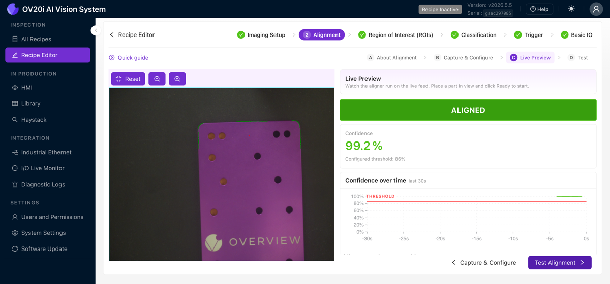
Live Preview
Click Live Preview Alignment, or the Live Preview sub-tab, to watch the aligner run on the live feed. A large ALIGNED badge shows the current state, alongside the live Confidence percentage against your configured threshold, a confidence-over-time graph, and readouts for matched angle, center X/Y, and alignment time. Move the part around, rotate it, push it into the corners, and try different valid parts. Confirm the confidence stays comfortably above the threshold.
Test
The Test sub-tab runs the aligner against a fixed set of saved captures instead of the live feed. Click Select From Library or Upload Captures to build a Test Set, then run it to find weak spots before the line is moving.
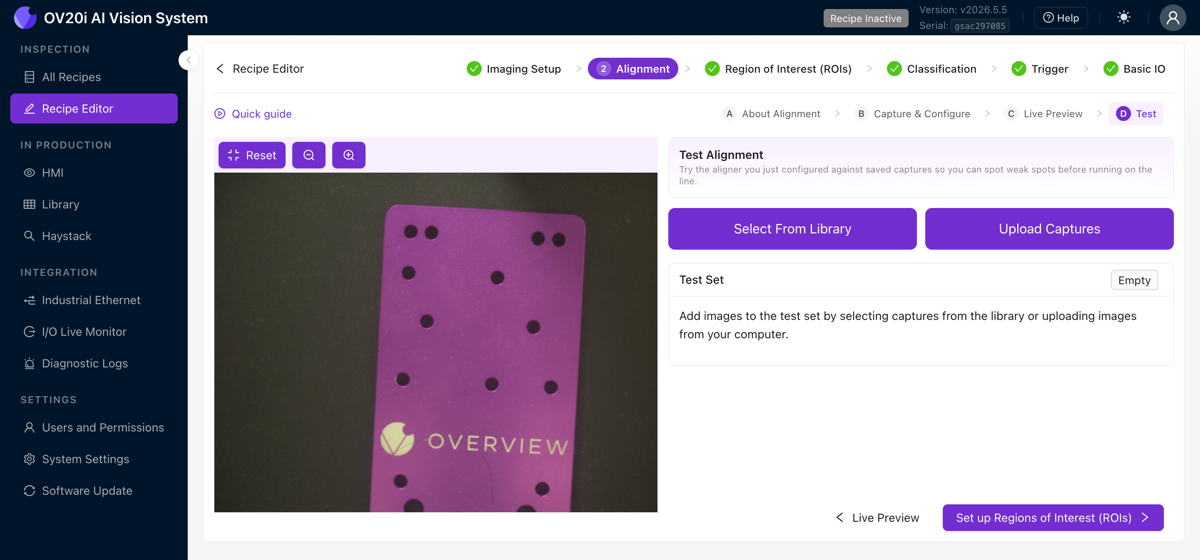
Alignment saves as you configure it, but always confirm it tracks in Live Preview before moving on. If you skip testing and discover unreliable alignment after setting up ROIs and training, you will have to redo everything downstream. That is the waterfall.
The 2D limitation (important to know)
The aligner works in 2D only: the flat plane that the camera sees. It handles:
- Left/right movement
- Up/down movement
- Rotation (spinning on the flat surface)
- Slight size changes (if Scale Invariant is on)
It does NOT handle:
- Warped or bent parts
- Parts tilted toward or away from the camera
- Any 3D variation
If your parts have 3D variation (one side closer to the camera than the other), skip the aligner entirely and use a segmenter with location-invariant training instead.
When to skip the aligner
You still need to capture a template image (the system requires it), but you can skip the aligner (in v2026.5, answer No, skip it under Use the aligner?; on older versions, toggle Skip Aligner) if:
- Your parts are in a precision fixture with less than 1-2 pixel movement
- You're using mechanical registration that guarantees exact positioning
- You're using a segmenter that doesn't need position tracking
Quick reference
| Setting | Recommended | Adjust when... |
|---|---|---|
| Template regions | 2-3, as far apart as possible | Alignment jitters → add regions, spread them out |
| Sensitivity | Lowest that gives solid green on your features | Not enough edges (red) → increase, then clean up noise |
| Rotation range | ±180° for most applications | Parts come in a known orientation → narrow the range |
| Confidence | 0.6-0.9 | Wrong matches → increase. Missing valid parts → decrease |
| Scale invariant | Off unless needed | Parts at varying distance from camera → enable |
Troubleshooting alignment
Common alignment problems and fixes
| Problem | Likely cause | Fix |
|---|---|---|
| ROIs don't move with the part | The aligner is turned off, or there are no template regions | Turn the aligner on; add template regions |
| Alignment jitters back and forth | Single region, or regions too close together | Add 2-3 regions far apart on opposite sides |
| Confidence stays near 0% | No usable edges in regions | Move regions to features with strong, clear edges |
| Matches the wrong thing | Features aren't unique enough, threshold too low | Choose more distinctive features; increase confidence threshold |
| Works on some parts, fails on others | Regions placed on features that vary between parts | Move regions to universal features (machined edges, holes) |
Alignment checklist
Before moving on, confirm:
- Template image captured from a good, defect-free part
- 2-3 template regions placed on strong, stable features
- Regions spread as far apart as possible on the part
- Noisy edges masked out with the cleanup tool
- Sensitivity tuned low enough to avoid noise, high enough for solid green on features
- Rotation range and confidence threshold set
- Live Preview tested; alignment tracks the part in all positions
Alignment working well? Move to Step 3: Regions of Interest (ROIs).