AI 驱动文档
您想了解什么?
第二步:对齐
对齐器是相机中最强大(也是最容易被误解)的部分。一旦你理解了它,一切都会豁然开朗。让我们简单地解释一下。
实际操作演示
在继续阅读之前,请先试用模拟器。关闭对齐器,然后移动滑块来平移和旋转部件。橙色 ROI 显示跟踪部件的感兴趣区域 (ROI),当对齐器无法继续跟踪时,绿色框会变为红色。
相机设置
模拟真实环境
移动生产线上的零件。
Legend
对齐的作用(以及为什么你需要它)
想象一下,你正在检测电路板上的螺丝。你已经在每个螺丝位置周围画了一个小框。但是当下一块板稍微向左偏移时会发生什么?或者旋转了一度呢?你的框现在指向了错误的位置。
对齐器解决了这个问题。 它会查看每张新图像,弄清楚部件移动到了哪里,并将所有检测框移动以匹配。就像有一个助手告诉你"板子向左移动了 3 个像素并旋转了 0.5 度,所以让我把你所有的框都移动一下以匹配。"
为什么这很强大: 当你的检测框可以随部件移动时,你可以把它们做得更小。而更小的框需要更少的数据来训练 AI。这是从良好对齐开始的级联效益。
为什么对齐是一切的基础
对齐器不仅仅是锦上添花。它是决定整个检测准确性的连锁反应中的第一张多米诺骨牌。下面是这个流程:
对齐 → 更小的 ROI → 所需训练数据更少 → 更准确的 AI
每一步都依赖于前一步:
- 良好的对齐 意味着即使部件在传送带上发生偏移或旋转,你的检测框也能精确跟踪部件。
- 精确的跟踪 意味着你可以绘制 更小的检测框(ROI)。你不需要添加额外的边距来应对部件移动。
- 更小的 ROI 意味着 AI 看到的是你关心的特征(螺丝、连接器、焊点)的紧密裁剪视图,而不是一片无关的背景。
- 更少的背景噪声 意味着 AI 学习所需的 训练图像更少,并且在生产中 错误更少。
对齐器不进行任何检测。它不判断通过或失败。它的唯一工作就是 动态移动你的检测框,使它们每次都能落在正确的位置。检测框完成实际的检测工作。这些框内的 AI 完成实际的判断。但如果框的位置不对,这些都无法正常工作。
可以把它想象成一条链条:对齐器 → ROI → 分类器/分割器。如果第一个环节薄弱,下游的一切都会崩溃。
工作原理:把它想象成拼图
对齐器通过匹配边缘来工作。这里有一个简单的思考方式:
- 你拍一张"参考照片"(模板图像),拍摄一个完美的部件
- 你在照片上指出特定的特征(角、边缘、孔洞),这些特征在每个部件上看起来都一样
- 每次新部件到达时,相机会在新图像中找到这些相同的特征
- 它计算差异:"这个部件向左偏移了 5 个像素,向上偏移了 2 个像素,倾斜了 1.2 度"
- 它将所有检测框 按这个偏移量精确移动
这就像玩一个匹配游戏。相机找到你向它展示的特征,并将它们用作锚点。
对齐的黄金法则
这一条规则将决定您的对齐是完美运行还是令人沮丧地抖动。原因如下:
这样理解: 想象一下您试图判断墙上的相框是否歪斜。
- 如果您只看一个角,您可能以为它是正的,但实际上它是倾斜的
- 如果您看两个相对的角(左上角和右下角),您可以立刻判断它是否歪斜,以及歪斜的精确程度
同样的原理适用于对齐器。如果零件一侧只有一个区域,那么 0.5 度的微小测量误差仍然是 0.5 度。但如果零件两侧各有一个区域,相同的误差经过平均后约为 0.05 度,精度提高了十倍。
关键:不应对齐到什么
这是对齐失败的首要原因。在您接触对齐器界面之前,请牢记以下两条规则。
1. 永远不要对齐到缺陷
缺陷是不可预测的。划痕、凹痕或缺失的螺丝在每个零件上看起来可能完全不同,或者根本不存在。
如果您让摄像头使用划痕作为锚点,那么当一个完好无损、没有划痕的零件来到产线上时,对齐将完全失败。摄像头将不知道在哪里放置您的检测框,整个系统将崩溃。
使用对齐器通过始终存在的特征(刚性边缘、加工角、钻孔)来找到零件。然后使用检测框来查找不可预测的缺陷。对齐器找到零件。检测框找到问题。
2. 永远不要对齐到可移动部件或标签
如果您对齐到可以独立于主体移动的东西,例如松散的电线、纸板翻盖或条形码贴纸,您将意外地误导摄像头将所有检测框移到错误的位置。
示例: 想象您将对齐器锚定到一个条形码贴纸。在下一个零件上,工人不小心将该贴纸向左放置了半英寸。摄像头看到贴纸移动,便假设整个零件向左移动了半英寸。它会移动所有检测框来进行补偿。但实际的金属零件并没有移动,只是贴纸移动了。现在所有的检测框都在查看错误的位置,导致全面的误判失败。
仅锚定到永久固定在零件刚体上的特征:加工边缘、模制角、钻孔、PCB 轮廓。永远不要锚定到标签、贴纸、电线、翻盖或任何人类可能意外重新定位的物体。
快速总结:应对齐什么 vs. 应避免什么
| 对齐到(永久、刚性特征) | 永远不要对齐到(可变或可移动) |
|---|---|
| 加工边缘 | 划痕、凹痕或缺陷 |
| 钻孔 | 条形码贴纸或标签 |
| PCB 轮廓 | 松散的电线或电缆 |
| 模制角或特征 | 纸板翻盖或包装 |
| 冲压金属边缘 | 胶带、粘合剂或标记 |
| 铸造或锻造几何形状 | 任何人类可能重新定位的特征 |
设置对齐器
OV20i Web 界面在 v2026.5 版本中进行了重新设计。请在相机 UI 的右上角查看您的软件版本,并选择匹配的选项卡。您的选择将应用于此设置流程的每个页面。
- 旧版本
- v2026.5 及更新版本
以下是对齐器设置界面的样子。您将看到模板图像,并带有彩色边缘高亮显示,表明对齐器正在使用哪些参考特征:
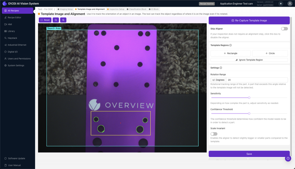
1. 捕获模板图像。 将良好的、无缺陷的零件放置在相机视野中。这将成为未来每个零件的比较参考。保持其光照充足、边缘清晰、清洁,并按照生产中将出现的方式定位。点击 Capture Template Image。
2. 添加模板区域。 点击 + Rectangle(或 + Circle)以创建模板区域,并放置 2-3 个。锚定在永不变化的特征上,例如机加工边缘、钻孔、PCB 轮廓、模制特征和冲压角。避免有纹理或可变的表面、缺陷出现的区域、反光眩光、微小细节,以及可能移动的标签或标记。
3. 理解边缘高亮。 当您放置一个区域时,会看到彩色高亮:
- 绿色高亮 = 检测到强而可用的边缘。这是您想要的。
- 红色高亮 = 边缘不足。将该区域移到具有更清晰边缘的特征上。
- 红点 = 对齐参考点(所有感兴趣区域 (ROI) 的中心)。
4. 使用 Ignore 工具清理噪声边缘。 这一步常被大多数人忽视,但它能带来巨大的差异。点击 Ignore Template Region,然后涂抹任何您不希望对齐器使用的边缘:随机背景纹理、眩光或反射、表面噪声、来自碎屑或标签的边缘,以及任何可能在零件之间发生变化的内容。
5. 调整灵敏度。

灵敏度滑块控制对齐器在模板区域内检测边缘的积极程度。将其设置为能在所有区域中提供坚实绿色高亮的最低值。值过低时区域会保持红色(特征不足以可靠匹配);值过高时绿色会扩散到背景纹理上,对齐器可能会锁定到噪声和抖动。
如果您需要更多边缘,请增加灵敏度滑块。但灵敏度越高,使用 Ignore 工具回头涂掉新出现的噪声就越重要。先撒大网,然后仔细挑出好鱼。
6. 设置旋转范围。
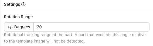
控制对齐器搜索的旋转角度范围:±180° 可在任何旋转角度找到零件(最适合大多数应用),±5-20° 仅在接近预期方向时匹配,±0° 是精确角度匹配。
如果您设置了像 ±5° 这样的窄范围,而进入的零件旋转了 10°,对齐器将无法匹配,您可以将此失败作为拒绝信号。这对于捕获方向不正确的零件很方便。
7. 设置置信度阈值。

对齐器需要多大的置信度才能确认找到正确的匹配。范围 0.0 到 1.0,推荐 0.6 到 0.9。值过高可能会错过有效零件;值过低可能会匹配错误的特征。
8. 启用尺度不变(如有需要)。 如果您的零件可能比相机近或远 ±10%(例如传送带上的高度变化),请启用此项。否则,保持关闭以获得最大速度。
9. 保存并测试。 这是最重要的一步,因此请勿跳过测试。 点击 Save 训练并部署对齐器,然后点击 Live Preview Mode 并移动零件:左、右、上、下;在您预期的范围内旋转它;将其放在帧的角落;尝试不同的有效零件。尝试破坏它。 如果对齐无法可靠跟踪,请立即修复。如果您继续进行 ROI 和训练,之后才发现问题,您将不得不重新做所有事情。这就是瀑布效应。
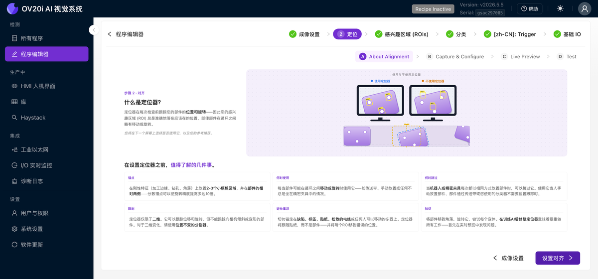
在程序编辑器中,打开步骤 2:对齐。它在顶部分为四个子选项卡:About Alignment、Capture & Configure、Live Preview 和 Test。Quick guide 按钮会运行该页面的简短引导教程。
关于对齐
从这里开始复习。此选项卡显示"使用与不使用对齐器"的对比图示,以及快速参考列,涵盖锚定对象、何时使用对齐器、何时跳过、对齐器的局限以及应避免的事项。
捕获与配置
这是主要的设置选项卡,是一个引导式清单,从上到下依次完成。
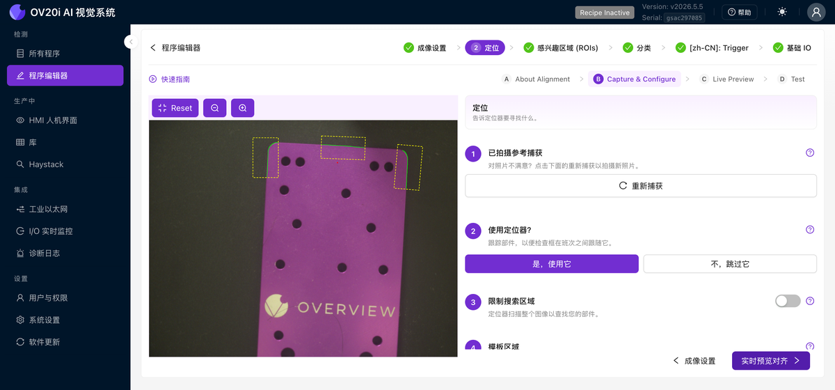
1. 已完成参考捕获。 选项卡打开时显示您捕获的参考图像。如果不满意,点击 Re-capture 重新捕获。点击 What makes a good reference photo? 查看完整清单:
- 显示整个零件,占画面的约 60% 至 80%。
- 使用均匀光照,避免强烈阴影或眩光。
- 按零件在生产中实际出现的方式放置。
- 捕获参考图像时保持一切静止。
- 使用干净、纯色的背景。
2. 是否使用对齐器?
- Yes, use it 跟踪零件的位移变化,使检测框随之移动。
- No, skip it 适用于零件被精密夹具固定且永不移动的情况。
3. 限制搜索区域。 默认情况下,对齐器会扫描整张图像以查找您的零件。打开此开关可将搜索限制在图像的某个区域,当零件总是出现在大致相同位置时,这能有效提速。
4. 查找关键边缘和特征。 点击 + Rectangle,在图像上拖动以绘制模板区域。放置 2 至 3 个区域,锚定在始终存在的特征上,如徽标、孔和锐利的角,并尽可能分散在零件两侧。点击区域以选中,然后使用出现的删除按钮将其移除。
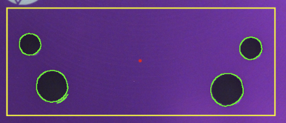
放置区域后,对齐器会高亮显示其中找到的边缘,并用红点标记对齐参考点:
- 绿色高亮表示强健、可用的边缘。这正是您想要的。
- 红色高亮表示找到的边缘不足。请将区域移至边缘更清晰的特征。
- 红点是对齐参考点,即所有区域的中心。
5. 清理多余边缘。 使用 Draw mask 涂抹您不希望对齐器使用的边缘,例如背景纹理、眩光、碎屑或零件之间会变化的内容,并使用 Erase mask 撤销。调整 Pen size 滑块进行精细操作,或使用 Clear all masks 重新开始。更干净的边缘会显著提高可靠匹配的概率。
6. 设置。 微调对齐器的严格程度。
Rotation Range 设置对齐器搜索的旋转角度范围,最大可达正负 180°(完整 360° 扫描)。将其缩窄可将方向偏差作为剔除信号。
Sensitivity 控制找到并匹配的边缘数量。使用仍能在特征上获得稳定绿色的最低设置。
Confidence Threshold 拒绝任何置信度低于阈值的对齐结果。0.6 至 0.9 的值适用于大多数零件。
Scale Invariant 应在零件相对相机距离可能正负变化 10% 时开启。为获得最高速度,请保持关闭。
如果需要更多边缘,请提高 Sensitivity。提得越高,回头使用 Draw mask 遮罩新噪声就越重要。撒下大网,然后仔细遮罩掉一切非稳定特征。
设置一个较窄的 Rotation Range,例如正负 5°,那么旋转了 10° 到达的零件就无法匹配。您可以将此失败作为方向不正零件的剔除信号。
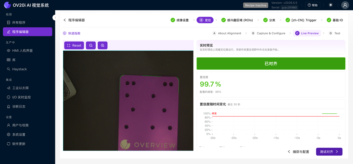
实时预览
点击 Live Preview Alignment 或 Live Preview 子选项卡,以观察对齐器在实时画面上的运行情况。一个大的 ALIGNED 标识显示当前状态,旁边还有相对于已配置阈值的实时 置信度 百分比、置信度随时间变化的图表,以及匹配角度、中心 X/Y 和对齐时间的读数。移动零件、旋转它、将其推到角落,并尝试不同的有效零件。确认置信度始终舒适地高于阈值。
测试
Test 子选项卡使对齐器针对一组固定的已保存捕获(而非实时画面)运行。点击 Select From Library 或 Upload Captures 来构建一个测试集,然后运行它以在产线启动前发现薄弱环节。
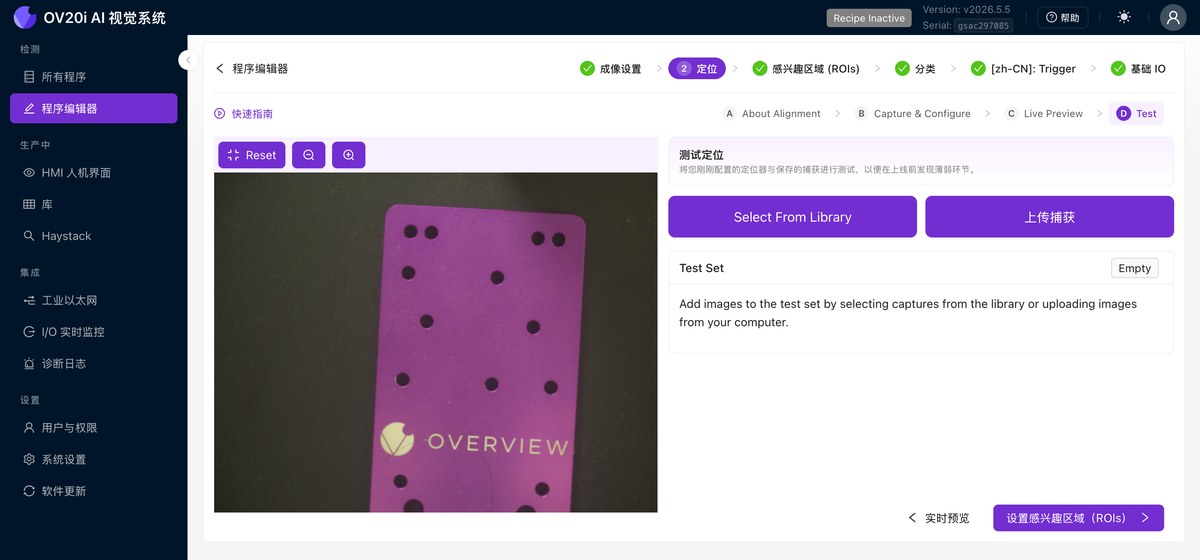
对齐配置会随您的设置自动保存,但在继续下一步之前,请务必在 实时预览 中确认其能正常跟踪。如果您跳过测试,在设置完 ROI 并完成训练后才发现对齐不可靠,那么您将不得不重做下游的所有工作。这就是瀑布效应。
2D 限制(必须了解)
对齐器仅在 2D 中工作:即相机所看到的平面。它可以处理:
- 左右移动
- 上下移动
- 旋转(在平面上转动)
- 轻微的尺寸变化(如果启用了尺度不变)
它不能处理:
- 翘曲或弯曲的零件
- 朝向或远离相机倾斜的零件
- 任何 3D 变化
如果您的零件存在 3D 变化(一侧比另一侧更靠近相机),请完全跳过对齐器,改用具有位置不变性训练的分割器。
何时跳过对齐器
您仍然需要捕获一张模板图像(系统要求如此),但在以下情况下您可以跳过对齐器(在 v2026.5 中,在 Use the aligner? 下回答 No, skip it;在旧版本中,切换 Skip Aligner):
- 您的零件位于精密夹具中,移动量小于 1-2 个像素
- 您正在使用保证精确定位的机械定位
- 您正在使用不需要位置跟踪的分割器
快速参考
| 设置 | 推荐值 | 何时调整... |
|---|---|---|
| 模板区域 | 2-3 个,尽可能远 | 对齐抖动 → 增加区域并将其分散 |
| 灵敏度 | 能让您的特征显示稳定绿色的最低值 | 边缘不足(红色)→ 增加,然后清除噪点 |
| 旋转范围 | 大多数应用 ±180° | 零件以已知方向到达 → 缩小范围 |
| 置信度 | 0.6-0.9 | 错误匹配 → 增加。漏掉有效零件 → 降低 |
| 尺度不变 | 除非需要,否则关闭 | 零件距离相机远近不同 → 启用 |
对齐故障排除
常见对齐问题及解决方法
| 问题 | 可能原因 | 解决方法 |
|---|---|---|
| ROI 不随零件移动 | 对齐器已关闭,或没有模板区域 | 打开对齐器;添加模板区域 |
| 对齐来回抖动 | 单一区域,或多个区域彼此过近 | 在相对的两侧添加 2-3 个相距较远的区域 |
| 置信度始终接近 0% | 区域内没有可用边缘 | 将区域移至具有强烈、清晰边缘的特征上 |
| 匹配到错误目标 | 特征不够独特,阈值过低 | 选择更具辨识度的特征;提高置信度阈值 |
| 部分零件可用,其他零件失败 | 区域放置在零件间存在差异的特征上 | 将区域移至通用特征(加工边缘、孔位) |
对齐检查清单
继续之前,请确认:
- 模板图像已从一个良好的、无缺陷的零件捕获
- 2-3 个模板区域已放置在强壮、稳定的特征上
- 区域在零件上尽可能分散
- 使用清理工具屏蔽了噪声边缘
- 灵敏度调整得足够低以避免噪声,足够高以使特征上呈现稳定的绿色
- 旋转范围和置信度阈值已设置
- 已测试实时预览;对齐在所有位置都能跟踪零件
对齐效果良好?前往第 3 步:感兴趣区域 (ROIs)。