AI-POWERED DOCS
What do you want to know?
LED Behavior Matrix
This page explains the behavior and purpose of each LED indicator on the OV20i camera, based on color and function.
note
Use this as a quick visual reference during setup, inspection, and troubleshooting.
LED Locations & Meanings
The OV20i includes 4 LED indicators on the top panel of the device, each with a distinct purpose:
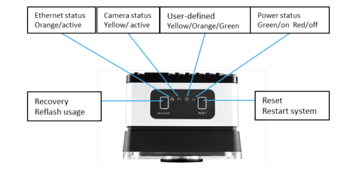
| LED Label | Color | Function |
|---|---|---|
| Ethernet Status | 🟠 Orange (Active) | Indicates network link or activity |
| Camera Status | 🟡 Yellow (Active) | Indicates image capture or streaming state |
| User-defined | 🟡/🟠/🟢 Yellow, Orange, Green | Reserved for software-defined behaviors |
| Power Status | 🟢 Green (On) / 🔴 Red (Off) | Indicates system power and health status |
Button Functions
| Button | Function | Notes |
|---|---|---|
| Recovery | Reflash usage (Support only) | Not to be used by customers |
| Reset | Restart system (Safe reboot) | Use if camera is unresponsive |
LED Quick Reference Table
| LED | State | What It Means |
|---|---|---|
| Ethernet (🟠) | Solid or blinking | Network link present and active |
| Camera (🟡) | Solid or blinking | Camera is running or capturing images |
| User-defined | Varies (🟢🟡🟠) | Reserved for internal diagnostics or software mapping |
| Power (🟢/🔴) | Green = On | System is powered and operational |
| Red = Off | No power detected (check power input and cable) |
Field Usage Notes
- Ethernet LED not lit? → Check cable seating, switch status, or static IP conflict
- Power LED red/off? → Confirm 24 VDC input and M12 connector seating
- Camera LED off during trigger? → Make sure camera is in hardware trigger mode
- User-defined LED stays orange? → May indicate fallback or non-ready state