AI-POWERED DOCS
What do you want to know?
Pinouts (M12 & Terminal)
This page provides complete pinout details for the OV20i smart camera’s connectors, including the 17-pin M12 Power & I/O interface and the M12 X-coded Ethernet port.
M12 A-Coded 17-Pin – Power & I/O Connector
The OV20i uses a male M12 17-pin connector for power, digital I/O, and reset functionality.
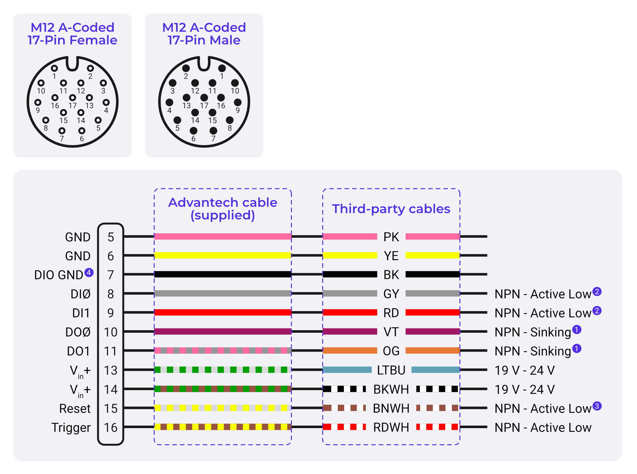
Legacy cable image: this diagram shows the original flying-leads colors used by the 3M & 5M cables. If your cable matches these colors, wire directly from it. If it does not match (10M cable, solid colors plus a Yellow/Green lead on pin 12), see the Wire Color Reference for the 3M & 5M vs 10M cable colors.
Pin Layout
| Pin | Signal Name | Function |
|---|---|---|
| 5, 6 | Power GND | 0V return path |
| 7 | DIO GND | Ground return for digital I/O |
| 8 | Digital Input 0 | NPN logic input |
| 9 | Digital Input 1 | NPN logic input |
| 10 | Digital Output 0 | NPN open collector |
| 11 | Digital Output 1 | NPN open collector |
| 12 | RS232 RX (optional) | Not used in standard configuration |
| 13, 14 | Power VIN (+24 VDC) | Primary power supply input |
| 15 | Reset Input | Pull low to reboot |
| 16 | Trigger Input | NPN trigger or dry contact |
| Others | Reserved / NC | Not electrically connected |
You do not need all four pins. The camera needs one +24 V connection and one ground: pins 13 and 14 are both Vin+ internally, and pins 5 and 6 are both power GND. One of each pair is enough to boot and run the camera.
Wiring both pairs is still the recommendation, because it halves the voltage drop along the cable. If the camera will not boot or browns out under load, connect both Vin+ pins and both grounds before suspecting the power supply.
The two ground wires can land in the same terminal on your power supply or terminal block. They do not need separate ports.
Wire Color Reference (M12 17-Pin)
The wire colors of the flying-leads Power & I/O cable depend on the cable length. The 3M and 5M cables use striped secondary colors, while the 10M cable uses solid colors and includes an extra lead on pin 12. Identify your cable by its length before wiring.
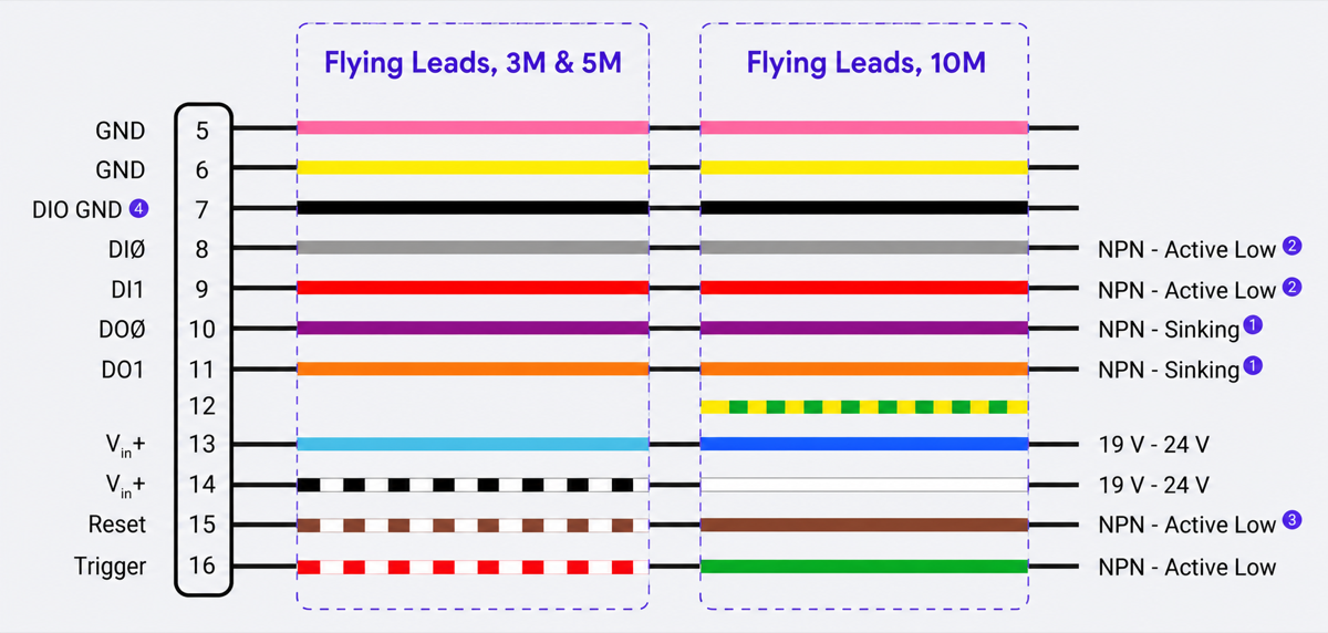
| Pin | Signal | Wire Color (3M & 5M Cable) | Wire Color (10M Cable) | Function |
|---|---|---|---|---|
| 5 | GND | Pink (PK) | Pink (PK) | Power Ground |
| 6 | GND | Yellow (YE) | Yellow (YE) | Power Ground |
| 7 | DIO GND | Black (BK) | Black (BK) | Digital I/O Ground |
| 8 | DI0 | Gray (GY) | Gray (GY) | Digital Input 0 - NPN Active Low |
| 9 | DI1 | Red (RD) | Red (RD) | Digital Input 1 - NPN Active Low |
| 10 | DO0 | Violet (VT) | Violet (VT) | Digital Output 0 - NPN Sinking |
| 11 | DO1 | Orange (OG) | Orange (OG) | Digital Output 1 - NPN Sinking |
| 12 | Reserved | No lead | Yellow/Green (YEGN) | Not connected internally |
| 13 | Vin+ | Light Blue (LTBU) | Blue (BU) | Power Input Positive (19-24V) |
| 14 | Vin+ | Black/White (BKWH) | White (WH) | Power Input Positive (19-24V) |
| 15 | Reset | Brown/White (BNWH) | Brown (BN) | System Reset - NPN Active Low |
| 16 | Trigger | Red/White (RDWH) | Green (GN) | Trigger Input - NPN Active Low |
| 1,2,3,4,17 | Reserved | - | - | Not connected |
On the 10M cable, the Yellow/Green lead on pin 12 is not a protective earth conductor, and the solid Green lead on pin 16 is the Trigger input. Do not wire by color convention alone. Leave the pin 12 lead unconnected.
M12 X-Coded Ethernet Connector
This 8-pin connector supports Gigabit Ethernet.
| Pin | Signal | Function |
|---|---|---|
| 1 | TD+ | Transmit Data (+) |
| 2 | RD+ | Receive Data (+) |
| 3 | TD– | Transmit Data (–) |
| 4 | RD– | Receive Data (–) |
| 5–8 | Bi-Directional | Gigabit pairs |
Use an X-coded M12 Ethernet cable for connectivity.
Digital I/O Electrical Summary
| Type | Logic | Trigger Method | Current Limit |
|---|---|---|---|
| Trigger Input | NPN-compatible | Pull to GND | – |
| Digital Inputs | NPN-compatible | Pull to GND | – |
| Digital Outputs | NPN Open Collector | Pulls to GND when active | 100 mA per line |
Digital outputs (DO0 / DO1) are NPN open-collector, sinking only. They pull the line to GND when active and cannot source +24 V. An external pull-up or load to +24 V must be provided for proper operation.
Always tie DIO GND (Pin 7) to your system or PLC ground.
Best Practices
- Use M12 screw-lock cables rated for industrial use
- Verify wiring polarity before powering up
- Add ferrules or strain reliefs in control panels
- Never hot-swap the M12 Power/I/O connector