AI 驱动文档
您想了解什么?
PLC 通信细节 (EtherNet/IP)
OV20i 视觉系统支持与基于 EtherNet/IP 的 PLC 进行实时通信。本指南解释如何配置循环 I/O 连接、映射数据结构,并使用 Overview 的 Node-RED 工具访问全局和 ROI 级别的检测结果。
查看此主题的实际操作:自动集成构建器
有关基本连接说明,请参见 连接到 PLC (EtherNet/IP, PROFINET).
概述
OV20i 作为 EtherNet/IP 适配器,而您的 PLC 作为扫描器(或主设备)运行。配置完成后,设备每个周期使用紧凑且可预测的格式交换结构化数据。
支持的功能
- 循环 I/O 通信 - 支持 20–10,000 毫秒的周期时间
- 数据吞吐量 - 每个方向最多 256 字节
- 自定义数据处理 - 作为活动配方的一部分读取/写入 Node-RED 数据
输入组件 (OV20i → PLC)
输入组件包含每个周期从 OV20i 发送到 PLC 的数据。这包括系统状态、检测结果、配方信息和可选的 ROI 细分。
输出组件 (PLC → OV20i)
输出组件包含从 PLC 发送到 OV20i 的控制数据。您可以使用它来触发检测、更改配方或传递自定义参数。
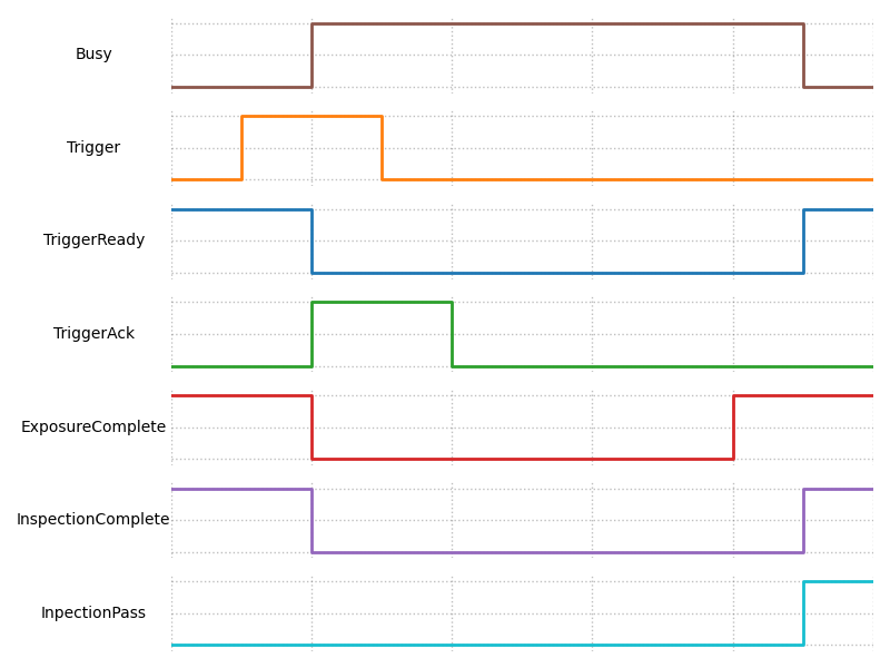
时序和握手行为
自定义数据支持
OV20i 可以接受或返回额外的自定义数据,作为您 Node-RED 流的一部分。
PLC → OV20i
- 写入外部标志、阈值或计数器,以影响 Node-RED 中的逻辑
OV20i → PLC
- 返回计算值、测量值、时间戳或条件输出
自定义数据适合放入组件的扩展部分,从核心信号和配方信息之后开始。
ROI 结果细分(仅限分类配方)
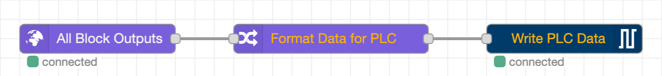
对于分类配方,您可以使用 Overview 的自定义 Node-RED 节点 Format data for PLC 将每个 ROI 的结果暴露给 PLC。
工作原理:
- 放置在 Node-RED 流中的所有块输出数据和发送数据到 PLC 之间
-
自动填充从输入组件第 16 字节开始的结构化 ROI 区域
-
每次检测支持最多 4 个 ROI
-
每个 ROI 包括:
- ROI ID
- 通过/失败位
- 置信度分数
- 未来使用的保留字节
Format Data for PLC 节点仅适用于分类配方。
默认 PLC 标签参考
本节提供输入和输出组件中每个标签的完整参考,包括字节偏移、位位置、数据类型和默认值。在配置您的 PLC 程序时,将其作为权威位图使用。
在相机 UI 中查看默认标签
- 打开 OV20i 网络界面(例如,
http://192.168.1.100)。 - 在左侧边栏中导航到 工业以太网。
- 选择您的活动协议(EtherNet/IP 或 PROFINET)。
- 页面显示当前的组件配置,包括输入/输出数据大小和连接状态。
- 此页面上显示的默认标签布局对应于下面的表格。
输入组件标签 (OV20i → PLC)
这些标签由 PLC 读取。相机在每个 I/O 周期中写入它们。
字节 0 -- 状态标志
| 位 | PLC 标签地址 | 标签名称 | 数据类型 | 描述 | 默认值 |
|---|---|---|---|---|---|
| 0 | I.Data[0].0 | 触发准备 | BOOL | 相机准备好接受触发。发送触发请求前必须为 HIGH。 | 0(启动后变为 HIGH) |
| 1 | I.Data[0].1 | 触发确认 | BOOL | 相机已接收到并接受触发请求。 | 0 |
| 2 | I.Data[0].2 | 配方切换确认 | BOOL | 相机已接收到并完成配方切换请求。 | 0 |
| 7 | I.Data[0].7 | 在线 / 启动完成 | BOOL | 相机已完成启动并在线。 | 0(启动后变为 HIGH) |
字节 1 -- 错误和状态标志
| 位 | PLC 标签地址 | 标签名称 | 数据类型 | 描述 | 默认值 |
|---|---|---|---|---|---|
| 0 | I.Data[1].0 | 触发错误 | BOOL | 在触发周期中发生错误。保持直到清除。 | 0 |
| 1 | I.Data[1].1 | 配方切换错误 | BOOL | 在配方切换过程中发生错误。保持直到清除。 | 0 |
| 6 | I.Data[1].6 | 正在处理 | BOOL | 相机正在处理(检查运行或配方切换)。在 HIGH 时请勿发送新命令。 | 0 |
字节 2 -- 检查结果标志
| 位 | PLC 标签地址 | 标签名称 | 数据类型 | 描述 | 默认值 |
|---|---|---|---|---|---|
| 0 | I.Data[2].0 | 曝光完成 | BOOL | 图像曝光已完成。 | 0 |
| 1 | I.Data[2].1 | 检查完成 / 结果可用 | BOOL | 检查处理已完成,结果有效。 | 0 |
| 2 | I.Data[2].2 | 检查通过 | BOOL | 最终的通过/失败结果。HIGH = 通过,LOW = 失败。仅在结果可用时为 HIGH 时有效。 | 0 |
字节 3--7 -- 保留
| 字节 | PLC 标签地址 | 标签名称 | 数据类型 | 描述 | 默认值 |
|---|---|---|---|---|---|
| 3 | I.Data[3] | 保留 | BYTE | 未来使用保留。 | 0x00 |
| 4 | I.Data[4] | 保留 | BYTE | 未来使用保留。 | 0x00 |
| 5 | I.Data[5] | 保留 | BYTE | 未来使用保留。 | 0x00 |
| 6--7 | I.Data[6]--I.Data[7] | 保留 | BYTE | 未来使用保留。 | 0x00 |
字节 8--9 -- 当前配方 ID
| 字节 | PLC 标签地址 | 标签名称 | 数据类型 | 描述 | 默认值 |
|---|---|---|---|---|---|
| 8--9 | I.Data[8]--I.Data[9] | 当前配方 ID | UINT (16 位) | 当前活动配方的 ID。与 O.Data[4] 比较以验证配方切换是否完成。 | 0 |
字节 10--11 -- 保留
| 字节 | PLC 标签地址 | 标签名称 | 数据类型 | 描述 | 默认值 |
|---|---|---|---|---|---|
| 10--11 | I.Data[10]--I.Data[11] | 保留 | BYTE | 预留供将来使用。 | 0x00 |
字节 12--13 -- 检查 ID
| 字节 | PLC 标签地址 | 标签名称 | 数据类型 | 描述 | 默认值 |
|---|---|---|---|---|---|
| 12--13 | I.Data[12]--I.Data[13] | 检查 ID | UINT (16 位) | 每次检查递增的 16 位计数器。用于将结果与特定触发器关联。 | 0 |
字节 14--15 -- 保留
| 字节 | PLC 标签地址 | 标签名称 | 数据类型 | 描述 | 默认值 |
|---|---|---|---|---|---|
| 14--15 | I.Data[14]--I.Data[15] | 保留 | BYTE | 预留供将来使用。 | 0x00 |
字节 16--256 -- ROI 结果汇编 / 来自 Node-RED 的自定义数据
| 字节 | PLC 标签地址 | 标签名称 | 数据类型 | 描述 | 默认值 |
|---|---|---|---|---|---|
| 16--256 | I.Data[16]--I.Data[256] | ROI 结果 / 自定义数据 | BYTE[] | 使用 "格式化数据为 PLC" Node-RED 块时,此区域填充结构化的 ROI 结果。否则可用于来自 Node-RED 流的自定义数据。 | 0x00 |
输出汇编标签 (PLC → OV20i)
这些标签由 PLC 写入。相机在每个 I/O 周期读取它们。
字节 0 -- 控制标志
| 位 | PLC 标签地址 | 标签名称 | 数据类型 | 描述 | 默认值 |
|---|---|---|---|---|---|
| 0 | O.Data[0].0 | 触发请求 | BOOL | 设置为高电平以触发检查。保持锁存,直到触发确认 (I.Data[0].1) 变为高电平,然后解除锁存。 | 0 |
| 1 | O.Data[0].1 | 配方切换请求 | BOOL | 设置为高电平以请求切换到 O.Data[4] 中的配方 ID。保持锁存,直到配方切换确认 (I.Data[0].2) 变为高电平,然后解除锁存。 | 0 |
字节 1--3 -- 保留
| 字节 | PLC 标签地址 | 标签名称 | 数据类型 | 描述 | 默认值 |
|---|---|---|---|---|---|
| 1 | O.Data[1] | 保留 | BYTE | 预留供将来使用。 | 0x00 |
| 2 | O.Data[2] | 保留 | BYTE | 预留供将来使用。 | 0x00 |
| 3 | O.Data[3] | 保留 | BYTE | 预留供将来使用。 | 0x00 |
字节 4--5 -- 配方 ID
| 字节 | PLC 标签地址 | 标签名称 | 数据类型 | 描述 | 默认值 |
|---|---|---|---|---|---|
| 4--5 | O.Data[4]--O.Data[5] | 配方 ID | UINT (16 位) | 要切换到的配方 ID。在设置配方切换请求位之前,将所需的配方编号写入此处。 | 0 |
字节 6--256 -- Node-RED 的自定义数据
| 字节 | PLC 标签地址 | 标签名称 | 数据类型 | 描述 | 默认值 |
|---|---|---|---|---|---|
| 6--256 | O.Data[6]--O.Data[256] | Node-RED 的自定义数据 | BYTE[] | 用户定义的数据,Node-RED 流程可以读取。使用此区域传递序列号、阈值、零件 ID 或其他任何参数给相机。 | 0x00 |
位映射图
以下基于文本的图表显示了两个组件的完整字节/位布局。每一行代表一个字节(或字节范围),每一列代表一个位位置(位 7 在左,位 0 在右)。
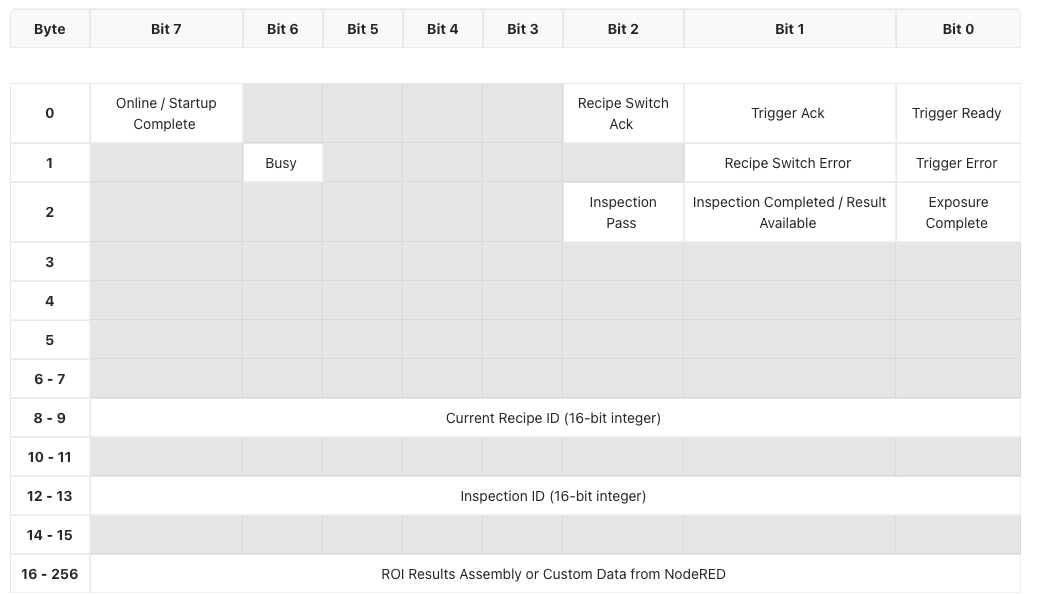
输入组件位图 (OV20i → PLC)
Byte │ Bit 7          │ Bit 6  │ Bit 5 │ Bit 4 │ Bit 3 │ Bit 2              │ Bit 1                      │ Bit 0
─────┼────────────────┼────────┼───────┼───────┼───────┼────────────────────┼────────────────────────────┼──────────────────
  0  │ Online/Startup │  ---   │  ---  │  ---  │  ---  │ Recipe Switch Ack  │ Trigger Ack                │ Trigger Ready
     │ Complete       │        │       │       │       │                    │                            │
─────┼────────────────┼────────┼───────┼───────┼───────┼────────────────────┼────────────────────────────┼──────────────────
  1  │  ---           │ Busy   │  ---  │  ---  │  ---  │  ---               │ Recipe Switch Error        │ Trigger Error
─────┼────────────────┼────────┼───────┼───────┼───────┼────────────────────┼────────────────────────────┼──────────────────
  2  │  ---           │  ---   │  ---  │  ---  │  ---  │ Inspection Pass    │ Inspection Completed /     │ Exposure
     │                │        │       │       │       │                    │ Result Available           │ Complete
─────┼────────────────┼────────┼───────┼───────┼───────┼────────────────────┼────────────────────────────┼──────────────────
 3-5 │  ---           │  ---   │  ---  │  ---  │  ---  │  ---               │  ---                       │  ---
─────┼────────────────┼────────┼───────┼───────┼───────┼────────────────────┼────────────────────────────┼──────────────────
 6-7 │                                     Reserved                                                     │
─────┼──────────────────────────────────────────────────────────────────────────────────────────────────────────────────────
 8-9 │                              Current Recipe ID (16-bit unsigned integer)                          │
─────┼──────────────────────────────────────────────────────────────────────────────────────────────────────────────────────
10-11│                                     Reserved                                                     │
─────┼──────────────────────────────────────────────────────────────────────────────────────────────────────────────────────
12-13│                              Inspection ID (16-bit unsigned integer)                              │
─────┼──────────────────────────────────────────────────────────────────────────────────────────────────────────────────────
14-15│                                     Reserved                                                     │
─────┼──────────────────────────────────────────────────────────────────────────────────────────────────────────────────────
16-  │                       ROI Results Assembly or Custom Data from Node-RED                           │
256  │                                                                                                  │
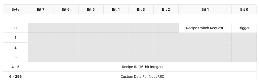
输出组装位图 (PLC → OV20i)
Byte │ Bit 7 │ Bit 6 │ Bit 5 │ Bit 4 │ Bit 3 │ Bit 2 │ Bit 1                 │ Bit 0
─────┼───────┼───────┼───────┼───────┼───────┼───────┼───────────────────────┼────────────────
  0  │  ---  │  ---  │  ---  │  ---  │  ---  │  ---  │ Recipe Switch Request │ Trigger Request
─────┼───────┼───────┼───────┼───────┼───────┼───────┼───────────────────────┼────────────────
 1-3 │                              Reserved                                │
─────┼──────────────────────────────────────────────────────────────────────────────────────────
 4-5 │                       Recipe ID (16-bit unsigned integer)            │
─────┼──────────────────────────────────────────────────────────────────────────────────────────
 6-  │                       Custom Data for Node-RED                       │
256  │                                                                      │
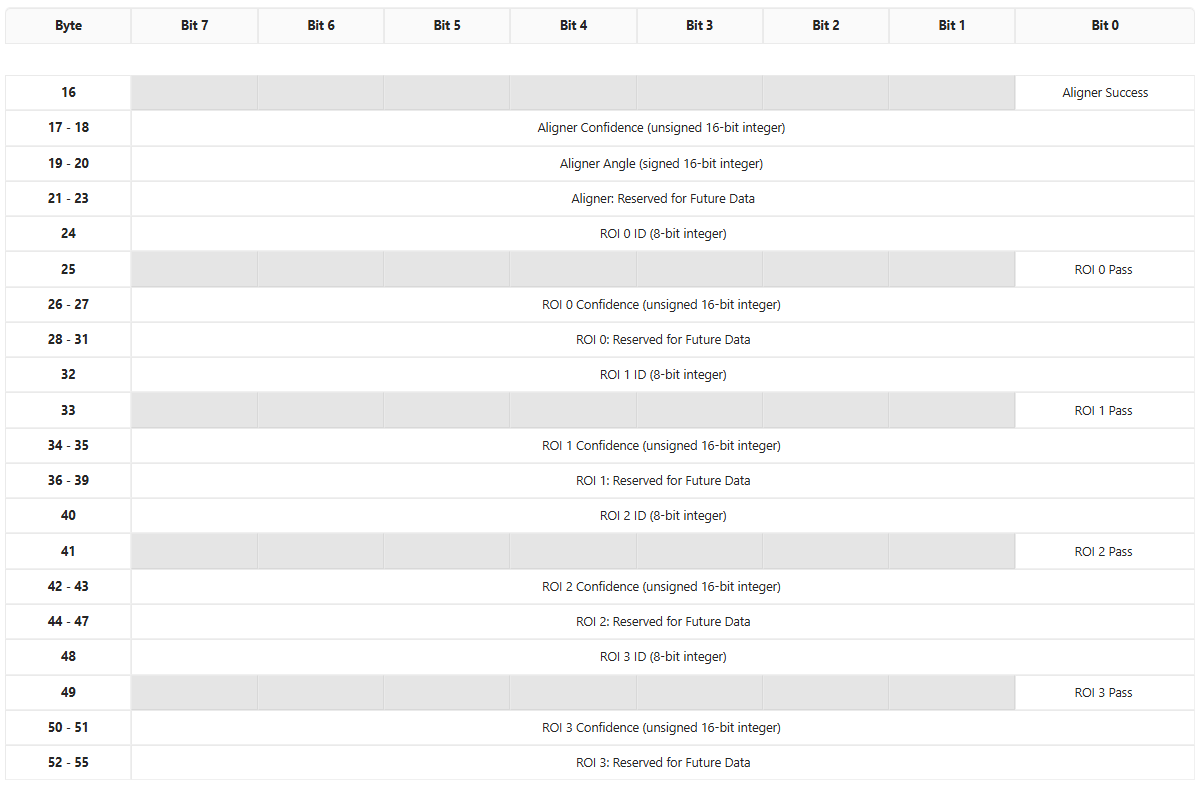
ROI 结果组装详细信息 (字节 16--55)
当使用 格式化数据为 PLC Node-RED 块与分类配方时,输入组装的字节 16 及以上将填充结构化对齐器和每个 ROI 数据,如下所示:
对齐器部分 (字节 16--23)
| 字节 | PLC 标签地址 | 标签名称 | 数据类型 | 描述 |
|---|---|---|---|---|
| 16, 位 0 | I.Data[16].0 | 对齐器成功 | BOOL | 如果对齐器成功定位了部件,则为 HIGH。 |
| 17--18 | I.Data[17]--I.Data[18] | 对齐器置信度 | UINT (16 位) | 对齐的置信度分数 (0--65535)。 |
| 19--20 | I.Data[19]--I.Data[20] | 对齐器角度 | INT (16 位,带符号) | 相对于模板的匹配角度。 |
| 21--23 | I.Data[21]--I.Data[23] | 保留 (对齐器) | BYTE | 保留用于未来的对齐器数据。 |
ROI 结果块 (字节 24--55)
每个 ROI 占用 8 字节。最多支持 4 个 ROI (ROI 0 到 ROI 3)。
ROI 块结构 (每 8 字节重复):
| 块内偏移 | 标签名称 | 数据类型 | 描述 |
|---|---|---|---|
| +0 | ROI ID | UINT8 (8 位) | ROI 的唯一数字标识符。 |
| +1, 位 0 | ROI 通过 | BOOL | HIGH = 此 ROI 通过,LOW = 此 ROI 失败。 |
| +2 到 +3 | ROI 置信度 | UINT (16 位) | 此 ROI 分类的置信度分数 (0--65535)。 |
| +4 到 +7 | 保留 | BYTE | 保留用于未来的每个 ROI 数据。 |
ROI 起始地址:
| ROI | 起始字节 | PLC 地址范围 | ID 地址 | 通过地址 | 置信度地址 |
|---|---|---|---|---|---|
| ROI 0 | 24 | I.Data[24]--I.Data[31] | I.Data[24] | I.Data[25].0 | I.Data[26]--I.Data[27] |
| ROI 1 | 32 | I.Data[32]--I.Data[39] | I.Data[32] | I.Data[33].0 | I.Data[34]--I.Data[35] |
| ROI 2 | 40 | I.Data[40]--I.Data[47] | I.Data[40] | I.Data[41].0 | I.Data[42]--I.Data[43] |
| ROI 3 | 48 | I.Data[48]--I.Data[55] | I.Data[48] | I.Data[49].0 | I.Data[50]--I.Data[51] |
缓冲区配置
在相机 UI 中查看默认标签
默认标签布局由相机固件定义,并对应于上述表格。要查看当前配置:
- 打开 OV20i 网络界面。
- 在左侧菜单中转到 工业 Ethernet。
- 选择您的协议 (EtherNet/IP 或 PROFINET)。
- 页面显示:
- 连接状态和设备信息
- 输入和输出组装大小(每个方向最多 256 字节)
- EDS 或 GSDML 文件下载链接(该链接也编码了默认组装结构)
EDS 文件(用于 EtherNet/IP)和 GSDML 文件(用于 PROFINET)都定义了默认数据大小。当您在 Studio 5000 或 TIA Portal 中添加相机模块时,这些描述符文件中的组装大小决定了每个周期交换的字节数。
创建自定义数据缓冲区
要在相机和 PLC 之间发送自定义数据(超出默认状态/结果标签),请使用 "Format Data for PLC" Node-RED 块:
- 从相机网络界面打开 Node-RED(导航到 Node-RED 编辑器)。
- 在您的配方流程中,将 "Format Data for PLC" 节点放置在 "All Blocks Output Data" 节点和 "Send Data to PLC" 节点之间。
- 配置字节顺序:
- 小端 用于 Allen-Bradley / Rockwell PLC
- 大端 用于西门子 PLC
- 该块会自动将分类 ROI 结果格式化为从输入组装的字节 16 开始的结构化布局(请参见上述 ROI 结果组装详细信息部分)。
对于完全自定义的数据缓冲区(不使用默认的 ROI 格式):
- 在您的 Node-RED 流中,使用 Function 节点构造一个具有所需字节布局的
msg.payload缓冲区。 - 将其连接到 "Send Data to PLC" 节点。
- 您的自定义字节将从字节 16 开始填充输入组装。
- 在 PLC 端,通过
I.Data[16]到I.Data[256]地址读取相应的数据。
更改标签分配
核心标签(输入组装的字节 0--15 和输出组装的字节 0--5)由相机固件固定,无法重新分配。这些是系统级信号(触发器、配方切换、状态、错误、配方 ID 和检查 ID)。
可配置区域为:
- 输入组装字节 16--256:由 Node-RED 填充。您可以通过配置 Node-RED 流来控制此处的数据。默认情况下,"Format Data for PLC" 块将此填充为 ROI 结果,或者您可以使用 Function 节点写入任意数据。
- 输出组装字节 6--256:由 Node-RED 读取。您可以将 PLC 中的任何数据写入这些字节,然后在 Node-RED 流中使用适当的输入节点读取它们。这对于将序列号、批次 ID、阈值或其他参数从 PLC 发送到相机非常有用。
从 PLC 发送自定义数据到相机(输出组装)
要将自定义数据从 PLC 传递到 Node-RED:
- 在您的 PLC 程序中,将值写入
O.Data[6]到O.Data[256]。 - 在相机上的 Node-RED 中,使用 PLC 输入数据节点读取这些字节。
- 在您的流逻辑中使用这些值(例如,阈值、序列号、条件参数)。
快速参考:标签地址备忘单
下表总结了在 PLC 编程中常用的标签,便于快速查找:
| PLC 地址 | 方向 | 信号名称 | 用途 |
|---|---|---|---|
I.Data[0].0 | 相机 → PLC | 触发准备 | 在触发前检查 |
I.Data[0].1 | 相机 → PLC | 触发确认 | 在此信号变为高电平后解除触发 |
I.Data[0].2 | 相机 → PLC | 配方切换确认 | 在此信号变为高电平后解除配方请求 |
I.Data[0].7 | 相机 → PLC | 在线 / 启动完成 | 确认相机已启动 |
I.Data[1].0 | 相机 → PLC | 触发错误 | 监控触发故障 |
I.Data[1].1 | 相机 → PLC | 配方切换错误 | 监控配方切换故障 |
I.Data[1].6 | 相机 → PLC | 正在忙碌 | 在高电平时不要发送命令 |
I.Data[2].0 | 相机 → PLC | 曝光完成 | 图像已捕获 |
I.Data[2].1 | 相机 → PLC | 结果可用 | 可以安全读取合格/不合格 |
I.Data[2].2 | 相机 → PLC | 检测合格 | 高电平 = 合格,低电平 = 不合格 |
I.Data[8]--I.Data[9] | 相机 → PLC | 当前配方 ID | 切换后验证配方 |
I.Data[12]--I.Data[13] | 相机 → PLC | 检测 ID | 将结果与触发器关联 |
O.Data[0].0 | PLC → 相机 | 触发请求 | 高电平保持以触发 |
O.Data[0].1 | PLC → 相机 | 配方切换请求 | 高电平保持以切换配方 |
O.Data[4]--O.Data[5] | PLC → 相机 | 配方 ID | 设置所需的配方编号 |
O.Data[6]+ | PLC → 相机 | 自定义数据 | 用户定义的数据用于 Node-RED |
I.Data[16]+ | 相机 → PLC | ROI 结果 / 自定义数据 | ROI 结果或自定义 Node-RED 输出 |