AI-POWERED DOCS
What do you want to know?
Measurement (Dimensional Inspection)
The Measurement block turns the OV80i from a defect detector into a dimensional inspection station. Instead of asking "is this part good or bad?", it asks "what is this part's diameter, gap, or angle, in millimeters?" — and gives you a number you can pass/fail against a tolerance.
Do not run a Measurement recipe with a standard (entocentric) C-mount lens. Standard lenses introduce perspective distortion and magnification changes with working distance — a part that sits 1 mm closer to the camera measures noticeably larger, and features near the edges of the frame measure differently than features in the center. The numbers you get out will be wrong by amounts larger than typical tolerances, and there is no calibration step that corrects for this.
A telecentric lens keeps magnification constant across the field of view and across small variations in working distance. It is the single piece of hardware that makes dimensional inspection actually accurate.
If your installation does not have a telecentric lens, stop here — switch to Classification or Segmentation for a pass/fail style of inspection, or contact support@overview.ai to spec the right optics before continuing.
Under the hood, a deep-learning model finds primitive features in the image (edges, circles, line segments, arcs) and then computes measurements between or about those primitives (radius of a hole, distance between two edges, angle between two lines). Because the camera is calibrated in px/mm, every result comes out in real-world units.
Learning objectives
By the end of this page you will be able to:
- Decide when Measurement is the right block (vs Classification or Segmentation)
- Calibrate the camera so a pixel maps to a known millimeter value
- Draw primitives (circles, lines, points, arcs) on the part and turn them into measurements (radius, distance, angle)
- Capture and label training images so the Measurement model learns to find primitives reliably
- Train, test, and deploy a Measurement model
- Wire results into pass/fail logic and read them on the camera's on-screen operator panel (the HMI, short for Human-Machine Interface)
When to use Measurement
| Use case | Right block |
|---|---|
| Is the hole diameter within 9.0 ± 0.1 mm? | Measurement |
| Is the gap between two parts under 0.5 mm? | Measurement |
| What angle is this bracket bent at? | Measurement |
| Is the label present or missing? | Classification |
| Is there a scratch on the surface? | Segmentation |
| What does the text on the part say? | OCR |
Measurement is the right tool any time a downstream system needs a number in physical units rather than a class label. If your spec sheet has a tolerance written on it, you want Measurement.
Segmentation can give you the area of a feature in pixels, but it does not snap to edges with sub-pixel accuracy and it does not give you geometric primitives. If you only need "is the stain bigger than X cm²", segmentation may be enough. If you need "the radius of this hole is 4.31 mm", use Measurement.
How Measurement works
The Measurement pipeline is four stages, in order:
- Capture and align. The camera triggers, captures a frame, and runs the aligner to lock the part to the template orientation. Every measurement is computed in the aligned frame, so a part rotated 10° still measures the same.
- Detect primitives. The trained Measurement model looks inside each ROI (Region of Interest — the rectangle you draw on the image to tell the camera "look here") and outputs geometric primitives: an edge segment, an arc/circle, or a line. Every recipe has one Main ROI plus optional Child ROIs for zooming in on specific features.
- Compute measurements. Each measurement you defined (e.g. "Radius of Circle 1", "Distance from Line A to Line B") is evaluated against the detected primitives. Results are reported in millimeters (or your chosen unit) thanks to the pixel-to-mm calibration.
- Pass/fail and output. The values are fed to the IO Logic block, where a Node-RED function decides PASS or FAIL based on your tolerances, and the result is pushed to the HMI, the PLC (the factory-floor controller), MQTT, and any other connected systems.
If your imaging is unstable, alignment drifts. If alignment drifts, the model sees the primitive in a different spot every time. If primitive detection is jittery, measurements are noisy. Fix problems at the earliest stage they appear. Re-tuning pass/fail thresholds will not fix bad alignment, and re-training the model will not fix bad imaging.
Step 1: Create a Measurement recipe
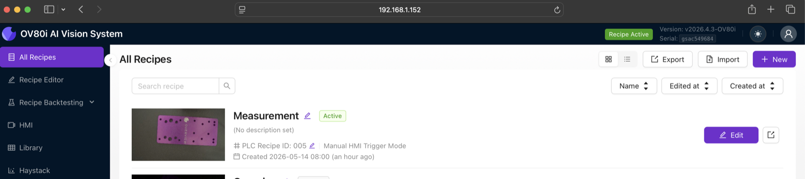
- Open the OV80i web interface in a browser (
http://<camera-ip>). The left sidebar shows All Recipes, Recipe Editor, HMI, etc. - Click All Recipes in the left sidebar.
- Click + New in the top-right corner. A modal titled Add A New Recipe opens.
- Enter a Name (e.g.
Hole_Diameter_Check) and an optional description, then click OK. - The new recipe appears in the list. Click Activate on its row, then choose Activate and go to editor in the confirmation dialog.
- The Recipe Editor opens. In the top bar, next to the recipe name, find the recipe-type combobox (it defaults to Classification). Click it and select Measurement. The AI Blocks row in the editor now highlights the Measurement block ready to be configured.
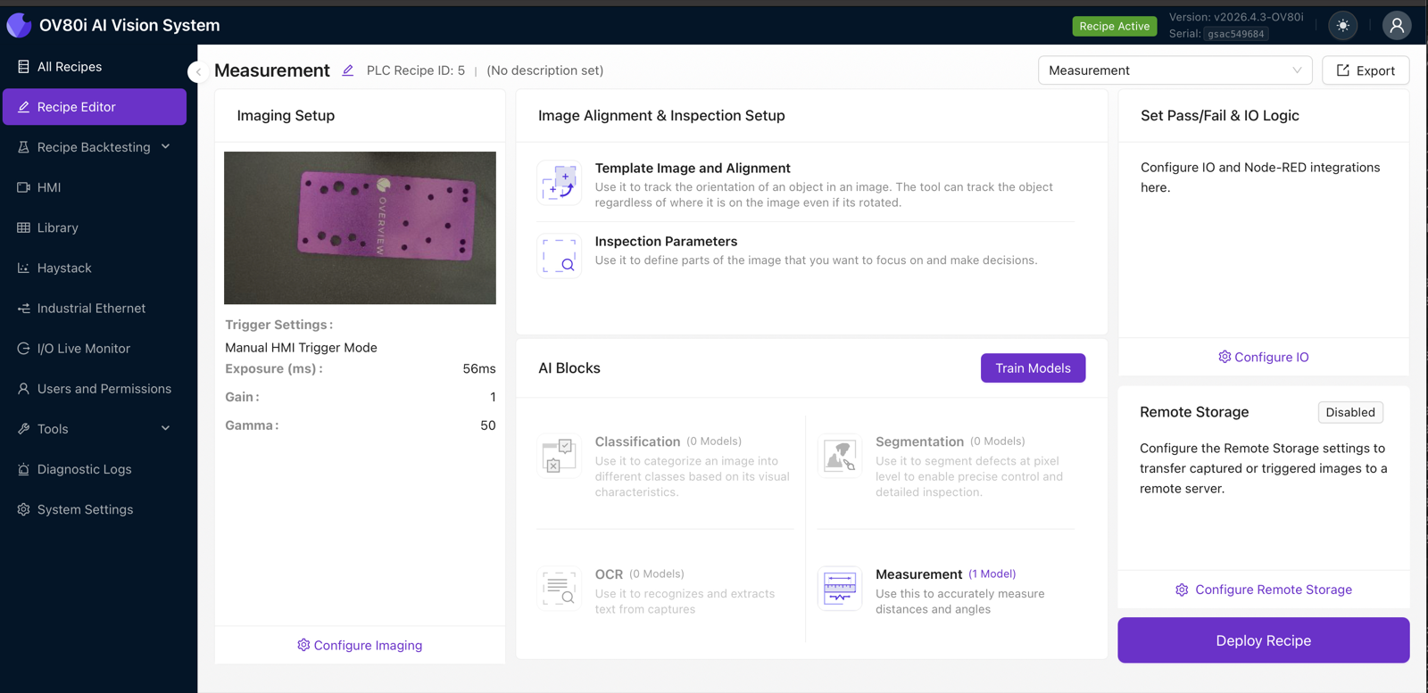
Each recipe holds exactly one Measurement model, but that model can carry many primitives and many measurements across multiple Child ROIs. Don't make a separate recipe per dimension — group all the dimensions on one part into one Measurement model so they share the same imaging and alignment.
Step 2: Imaging Setup
Click Configure Imaging in the editor to open Imaging Setup. This is the same imaging panel used by every recipe — see Imaging Setup Fundamentals — with one extra responsibility for Measurement: the part must be in sharp focus, with no motion blur, every cycle. Sub-pixel edge accuracy depends on it.
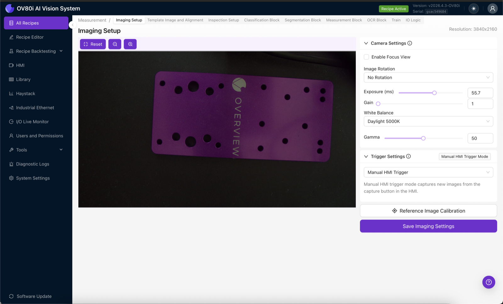
Settings that matter most for Measurement:
- Exposure. Set the part well-exposed but not blown out. Saturated highlights destroy edge detail.
- Gain. Keep gain at 1 if you can. Higher gain adds noise, and noise shifts edges by half a pixel at a time.
- Gamma. Default 50 is fine for most parts. Raise it if dark edges are hard to see.
- Image Rotation. Leave at "No Rotation" unless your fixture forces a sideways camera mount.
- Trigger Settings. Manual HMI Trigger is fine for setup. Switch to a digital sensor or PLC trigger for production.
Long exposure + moving conveyor = blurred edges. A 2-pixel blur on a 17 px/mm calibration is a ±0.06 mm error before you even start. Either freeze the part with a strobe or drop exposure low enough that motion in one frame is under 1 pixel.
Click Save Imaging Settings when done.
Step 3: Calibrate pixels to millimeters
This is the step that distinguishes Measurement from every other block. Without calibration, the camera only knows pixels — and a pixel is a different size on every install. Calibration teaches the camera "this many pixels on the sensor equals this many millimeters in the real world."
- In Imaging Setup, click Reference Image Calibration (bottom of the right panel).
- Capture or upload a reference image that contains a known dimension — typically a calibration target, a precision-machined feature on the fixture, or a known-good part where you've measured a dimension with calipers.
- Open the Measurement Calibration section. Confirm the unit (default
mm). - Click Measure on Image. Click two points on the image that span a known distance (e.g., the center-to-center distance between two pins, or the diameter of a gauge pin).
- The camera reports the measured pixel distance (e.g. "Measured: 159 px"). Type the real-world value in millimeters (e.g.
9.0) and click Finish. - The px/mm value populates automatically — for this recipe in the screenshots below, calibration came out to 17.621 px/mm, meaning one millimeter of the part occupies ~17.6 sensor pixels.
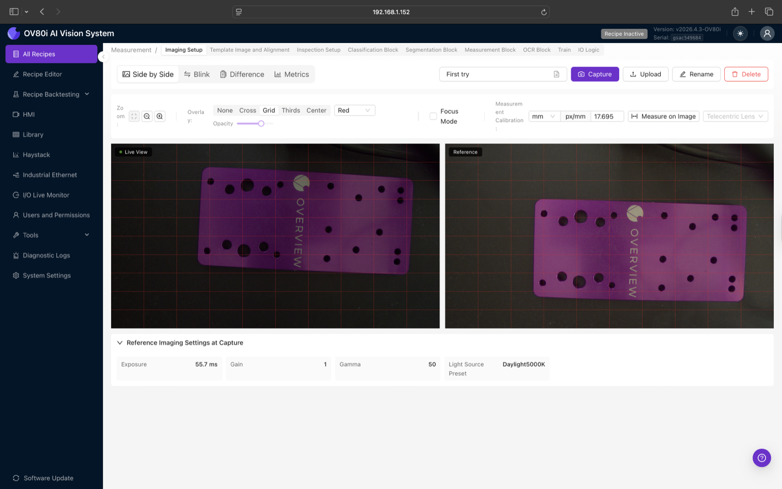
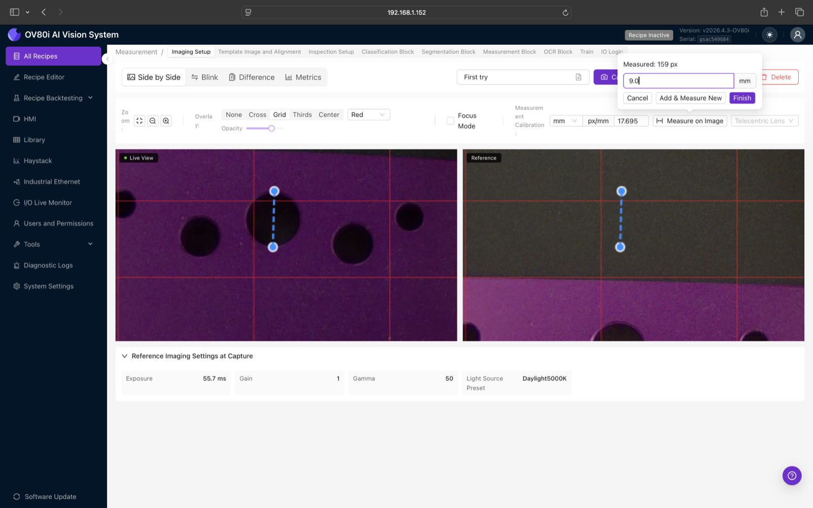
The px/mm number is tied to the lens, working distance, and sensor. If you change the lens, refocus, move the camera, or swap fixtures, recalibrate. A calibration that's 1% off becomes a measurement that's 1% off — on a 10 mm dimension, that's 0.1 mm of pure systematic error, often more than your tolerance.
Calibrating off a 2 mm feature multiplies any pointing error by 5x compared to calibrating off a 10 mm feature. Always calibrate against the longest known dimension that fits cleanly in the frame.
Step 4: Template Image and Alignment
Measurement requires alignment. The model is trained against primitives in fixed positions on the part; if the part shifts or rotates, the aligner has to compensate so the model still sees the primitives in the same image coordinates.
- From the Recipe Editor, click Template Image and Alignment under "Image Alignment & Inspection Setup".
- Capture a clean reference image with the part well-positioned, then draw the Search Area (cyan box) around the area of the image where the part may appear, and the Template Region (yellow box) tightly around the part itself.
- Choose an Aligner Type: Classical for edge-rich parts, Deep Learning for textured parts — see AI Aligner (Deep Learning) for the decision matrix.
- Tune Rotation Range, Sensitivity, and (for Classical) the ignore regions until alignment is stable across captures.
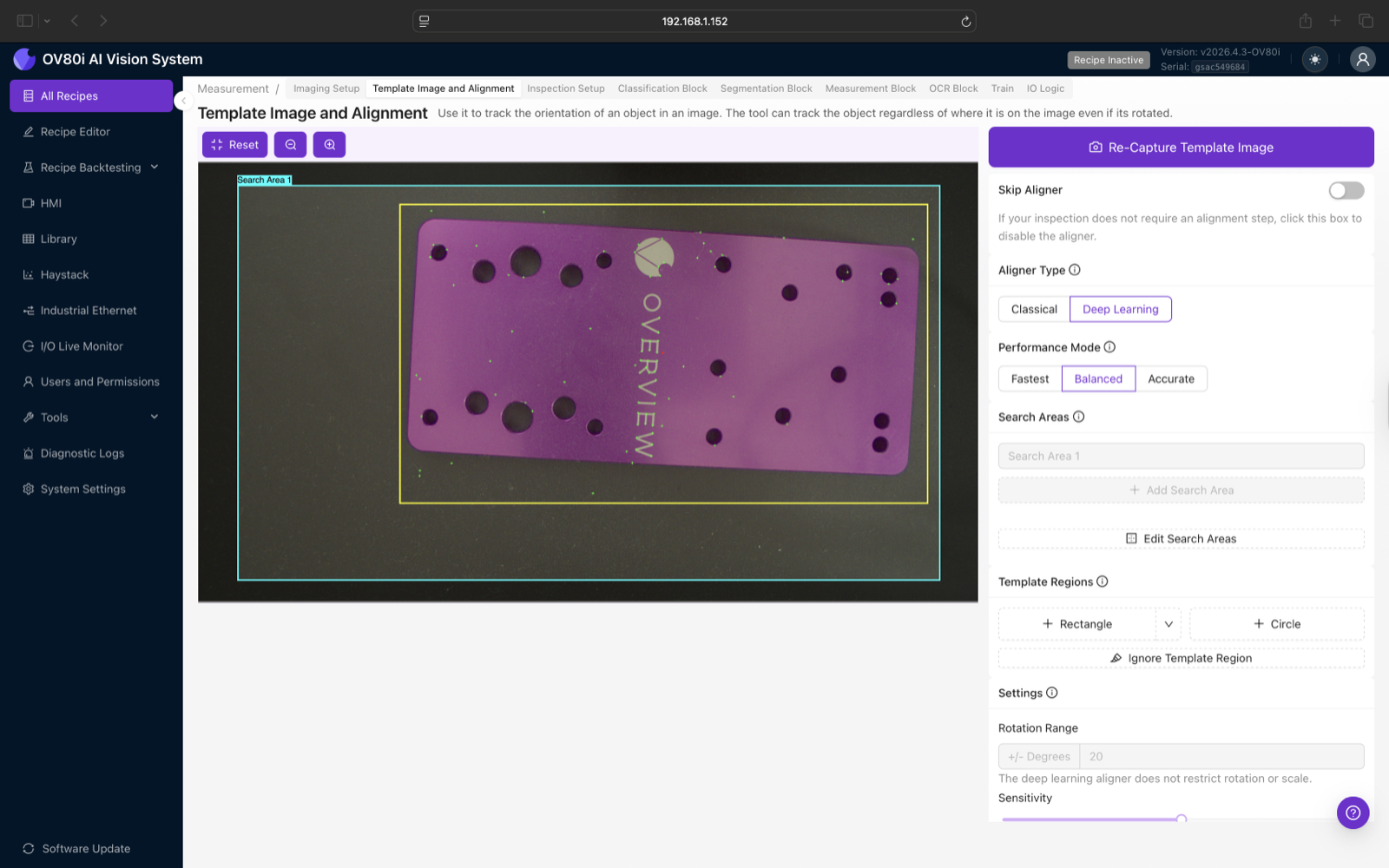
The AI Aligner's "Scale Invariant" option lets the matcher tolerate parts that are slightly closer or farther from the camera. Do not enable it on a Measurement recipe. Scale Invariance silently rescales the frame to match the template, which means a part that is 1% farther from the camera measures the same as a part at the correct distance — and your px/mm calibration is suddenly wrong. Keep Scale Invariant off and control the working distance with mechanical fixturing instead.
The "Skip Aligner" toggle is fine for Segmentation or Classification recipes that look at the whole image, but a Measurement recipe with no aligner will produce nonsense the moment a part shifts a millimeter. Always configure alignment for Measurement.
Step 5: Inspection Setup — Main ROI and Child ROIs
The Inspection Setup screen defines where in the aligned image the Measurement model should look. There is one Main ROI (covers the whole region of interest) and, optionally, one or more Child ROIs (zoom in on specific features).
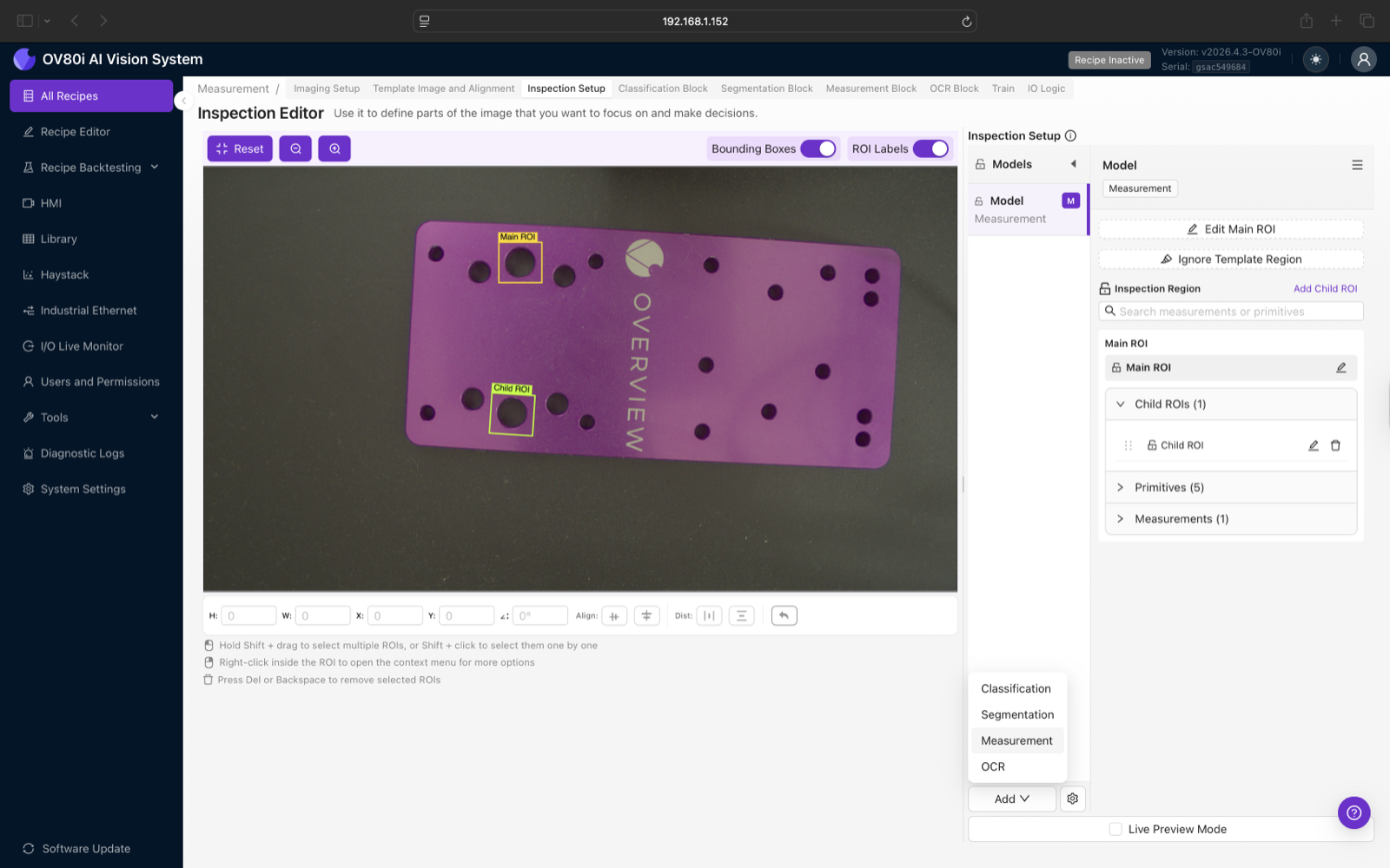
- The Main ROI box already exists when the Measurement block is added — drag its corners until it covers the area you want to measure. Most recipes use a single Main ROI that covers the whole part.
- To inspect multiple discrete features (two holes on opposite sides of a bracket, for example), click Add Child ROI for each one and position it tightly around the feature.
- Each ROI gets its own copy of the model's primitive predictions. A Main ROI with five Child ROIs means the model runs six times per capture.
A tight Child ROI around a single hole gives the model a clean view of one feature, makes labeling unambiguous, and keeps inference fast. A giant Main ROI covering ten holes means the labeler has to disambiguate ten primitives in every image, and the model has more visual noise to ignore.
The bar above the canvas has H / W / X / Y / ∠ inputs for precise ROI placement, Align and Distribute buttons for laying out ROIs evenly, and a Bounding Boxes + ROI Labels toggle to clean up the overlay while you work. Right-click any ROI for a context menu (copy, paste, lock, delete).
Step 6: Define primitives
Open the Primitive Editor by clicking Edit Main ROI (or Edit on any Child ROI). This is where you draw the geometric shapes the model will learn to find. Each ROI starts with four locked System primitives — Top / Bottom / Left / Right edge of the ROI itself — which you can use as reference geometry for distance measurements without drawing anything new.
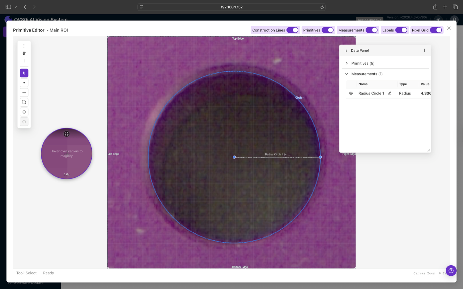
Available primitive types (left toolbar):
| Tool icon | Primitive type | What it captures | Where it shows up |
|---|---|---|---|
| Line | Segment | A straight edge | Part edges, slots, references |
| Arc / Radius | Circle | A radius + center | Holes, pins, fillets, curved features |
Hover any tool icon to see its name; the status bar at the bottom of the editor shows the active tool — e.g. "Tool: Arc — Click to place the first point".
To draw a primitive:
- Click the tool icon in the left toolbar (e.g. Line or the radius/arc tool). The status bar shows the active tool name.
- Click on the image at the points the tool needs. For a circle/arc, click three points around the edge of the feature. For a line, click two endpoints.
- The primitive appears in the Data Panel on the right, under the Primitives section.
- Rename it to something meaningful (
Hole_A,Top_Edge_of_Slot) by clicking the pencil icon next to its name. Good names make measurements readable later.
The toggle row above the canvas (Construction Lines, Primitives, Measurements, Labels, Pixel Grid) controls what's drawn on top of the image — turn them off to declutter while drawing, turn them back on to verify.
Hover the canvas while drawing and a 4x magnifier appears in the corner. Sub-pixel edge placement matters: a primitive placed one pixel off, multiplied across 1000 cycles, is what separates a usable measurement from a noisy one.
The arc tool fits a circle through three points on the edge of the feature. Place those three points far apart around the rim, not bunched at the top. A bunched-up trio gives a wobbly fit that the model will inherit.
Step 7: Define measurements
Primitives are the raw geometry; measurements are the numbers you actually care about. Each measurement references one or two primitives and computes a value from them.
Available measurement types:
| Measurement | Inputs | Output |
|---|---|---|
| Radius | One circle/arc | Radius of the circle in mm |
| Distance | Two primitives (point-to-point, point-to-line, line-to-line) | Shortest distance in mm |
| Length | One line segment | Length of the segment in mm |
| Angle | Two lines | Angle between them in degrees |
| X / Y position | One point | Coordinate of the point in the aligned frame |
To define a measurement:
- In the Primitive Editor's right-hand Data Panel, expand the Measurements section.
- Click the + / Add measurement button at the top of the Measurements section. A small form opens.
- Choose the measurement type (Radius / Distance / Angle / Length / etc.) from the dropdown.
- Pick the primitive(s) it should reference. A Radius measurement takes one circle; a Distance takes two primitives.
- Name the measurement descriptively (
Hole_A_Diameter,Slot_Gap). This name shows up on the HMI and is the key your Node-RED Function uses to read the value, so keep it stable. - Click outside the form or press Enter to save. The new measurement appears in the Measurements table with its live value computed from the template image.
You can mix and match: a single ROI can hold five primitives and ten measurements derived from them. The screenshot above shows one Circle 1 primitive with a Radius Circle 1 measurement that reports 4.306 mm.
The locked Top / Bottom / Left / Right Edge primitives that come with every ROI are valid measurement inputs. If you need "distance from the bottom of the slot to the bottom of the ROI", you don't need to draw a new line — reference the system Bottom Edge directly.
Step 8: Label training images
Drawing primitives on the template gives the model one example. Production needs at least 10–20 examples so the model learns to find the primitives under real-world variation (lighting drift, surface scratches, color batches).
- In the Recipe Editor, click Measurement Block from the top navigation, or Measurement under AI Blocks.
- Click Capture to grab a new frame, or Import Capture to bring one in from the Library.
- For each capture, draw the same primitives you defined on the template — at the same locations on each new image of the part.
- Click Save Annotations when each capture is labeled.
- Navigate Previous / Next to walk through every capture.
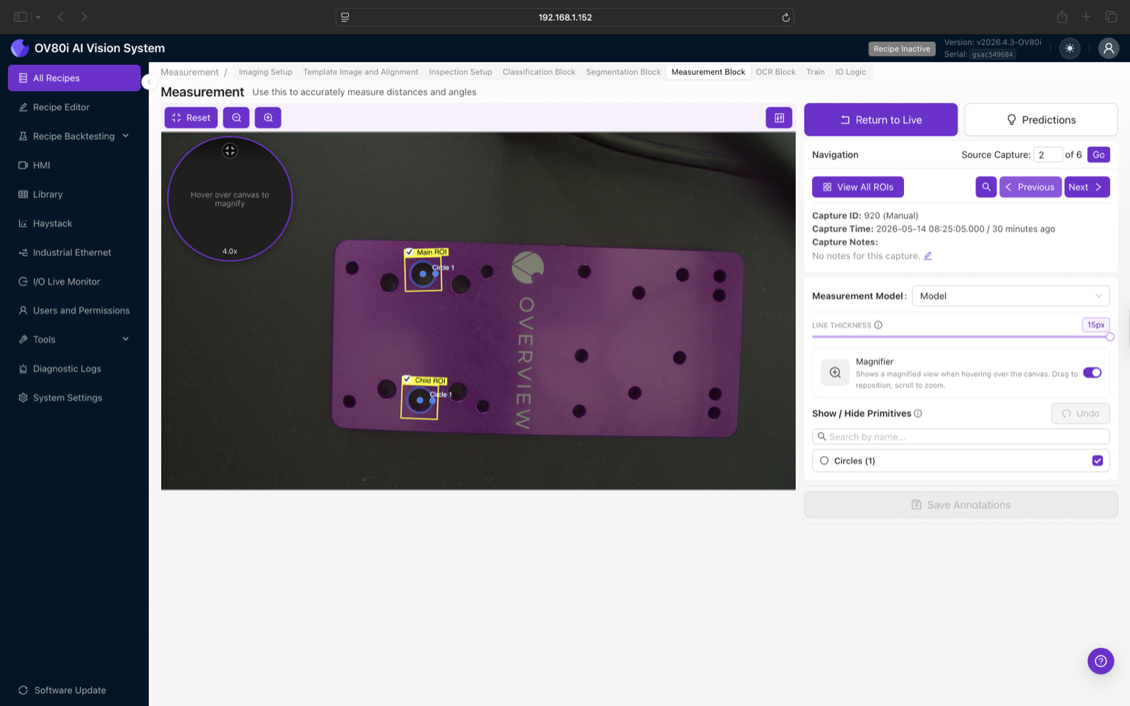
Twenty captures of the same part in the same position teach the model very little. Ten captures across a range of part rotations, slight position offsets, lighting variations, and surface conditions teach it everything it needs. Vary deliberately.
If "Circle 1" is the top-left hole on capture 1, it has to be the top-left hole on capture 2. Mixing up which physical feature a named primitive points to teaches the model contradictions, and the contradictions show up as 10x noisier predictions in production.
Step 9: Train the model
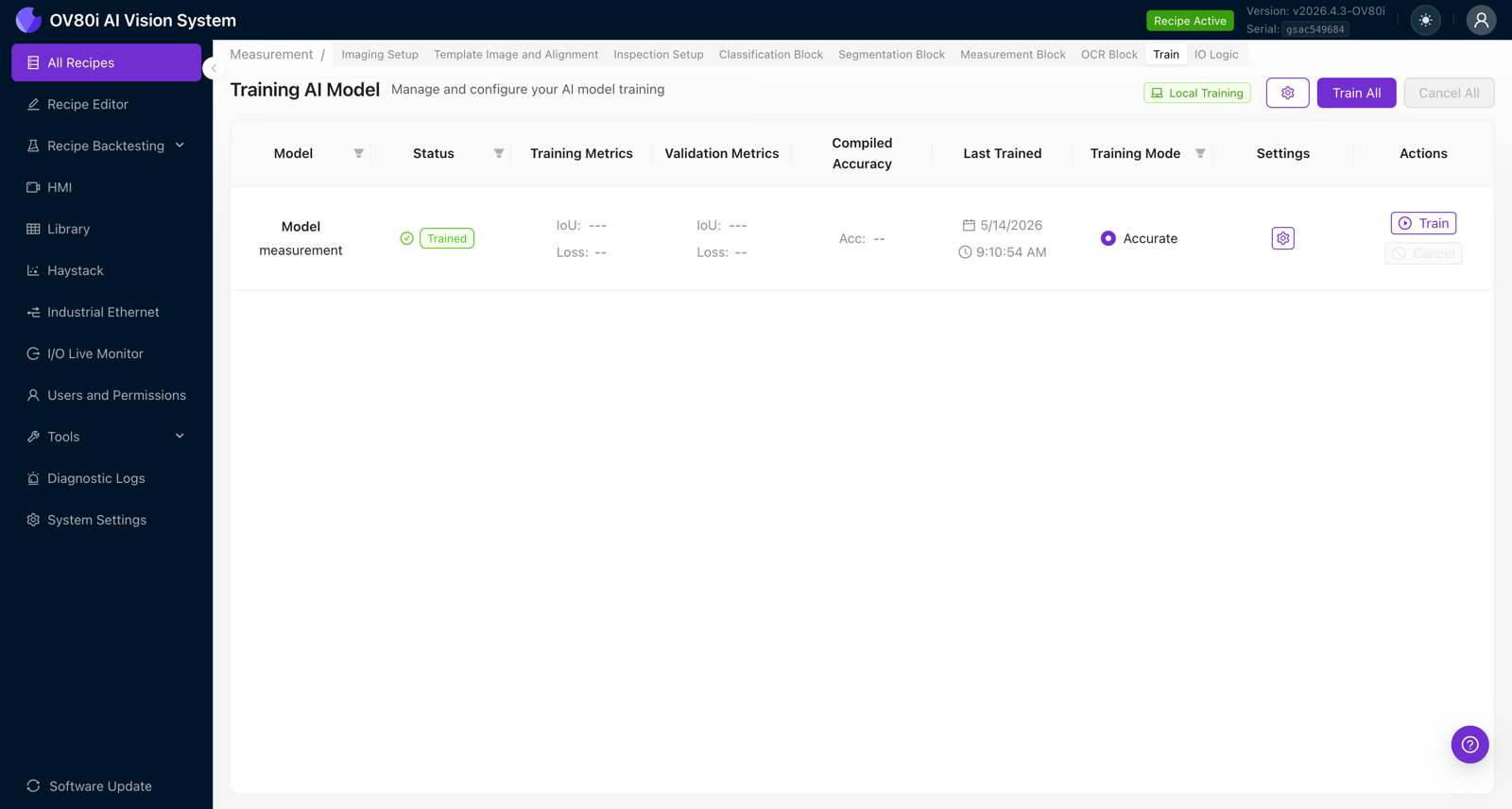
- From the Measurement Block view or the Recipe Editor, open the Train tab.
- Find the measurement row. Confirm the Training Mode — for Measurement, Accurate is the default and recommended. Faster modes exist for quick iteration but trade off precision.
- Click Train on the row (or Train All to train every block in the recipe).
- The Training AI Model modal shows live progress: Mean IoU (blue, climbing), Loss (red, falling), and the iteration counter (e.g. 200/200).
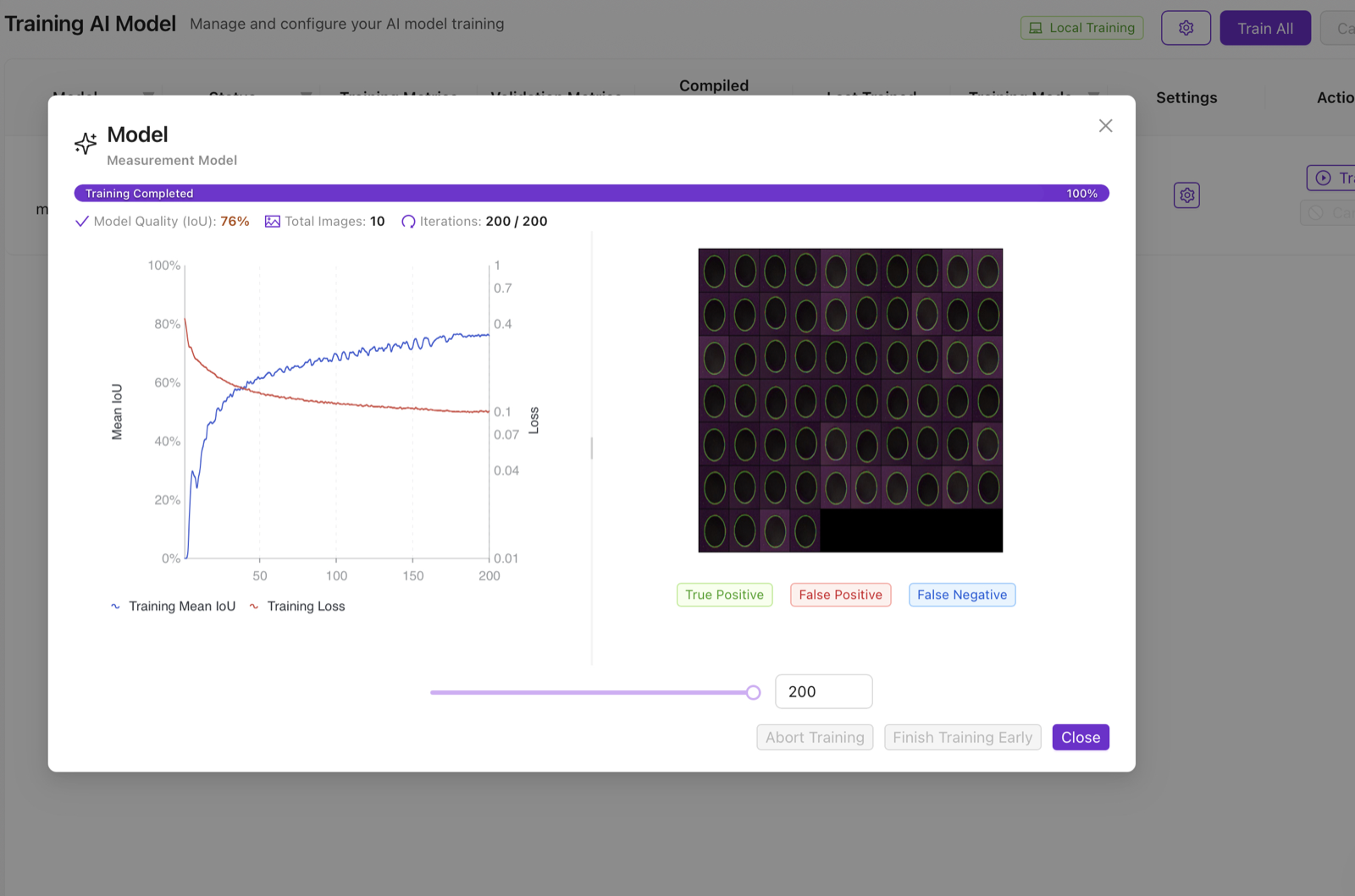
What to look for:
- IoU climbs and Loss falls as iterations go up. If they're both flat early, more images or better labels are needed.
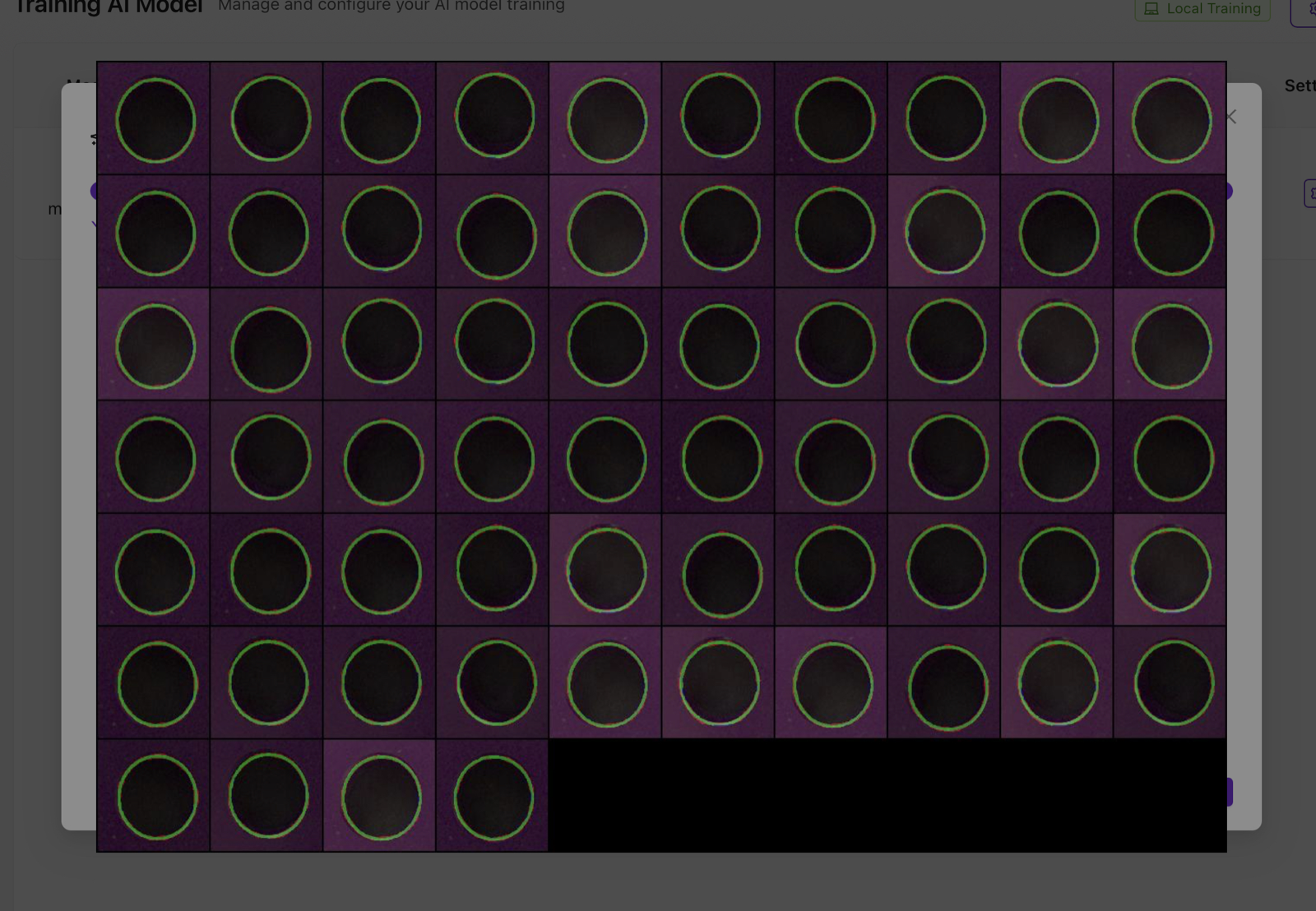
- The thumbnail grid on the right shows training crops with predicted primitives drawn (True Positive in green, False Positive in red, False Negative in blue). Skim it — if a crop is in the red/blue legend, look at its labels.
- Model Quality (IoU) is reported when training finishes. For Measurement, anything above 70% is usable; above 85% is excellent.
Don't aim for a perfect first model. Train with 10 captures, run Live Preview on a fresh part, see where the predictions drift, then add 5 more captures targeted at the failure mode and retrain. Three short iterations beats one long one.
Step 10: Test and verify
- Back in the Measurement Block view, toggle Live Preview Mode on.
- Trigger captures with the Test button (or Capture in the HMI) and watch the predicted primitives overlay onto live frames.
- Compare predicted dimensions to caliper measurements on the same physical part. The two should agree within your tolerance budget.
- Move the part around (within alignment limits) and confirm the measurement value stays stable across captures.
The camera tells you 4.306 mm. Pick up the part, measure it with calipers, and see if you also read 4.3 mm. If the camera and calipers disagree by more than your tolerance, the problem is almost always calibration (step 3) — recalibrate against the longest dimension on the fixture and try again.
Step 11: Wire pass/fail logic
The model produces numbers; the IO Logic block turns those numbers into a PASS or FAIL.
- From the Recipe Editor, click Configure IO (or the IO Logic tab).
- Drag in an All Block Outputs node, a Function node, and a Final Pass/Fail node. Wire them together.
- Double-click the Function node and write the tolerance check. Below is the shape of the logic — measurement results arrive under the Measurement block's portion of
msg.payload, keyed by the names you set in the Primitive Editor. The exact payload structure can shift between firmware versions, so wire in a Debug node once and inspect the livemsgto confirm the field names before relying on them.
// PASS if hole radius is within 4.30 ± 0.10 mm
// Adjust the path below to match the payload from your camera's
// Debug node — the Measurement block emits an array of measurement objects
// each with a name and a numeric value in mm.
const measurements = msg.payload.measurement?.measurements ?? [];
const radius = measurements.find(m => m.name === 'Radius Circle 1');

if (!radius) {
  msg.payload = false; // no result = fail
  return msg;
}

const value = radius.value;       // value in mm
const target = 4.30;
const tolerance = 0.10;

msg.payload = Math.abs(value - target) <= tolerance;
return msg;
- Click Deploy to push the flow live.
The Function node looks up measurements by the names you assigned in the Primitive Editor. Rename a measurement and the flow breaks until you update the node. Keep names stable once production rolls.
For parts with several dimensions to check, build an Array.every(...) over a list of {name, target, tolerance} objects. One Function node can validate every dimension on the part, and a single failure short-circuits the whole inspection to FAIL.
Reading results on the HMI
After deploying, switch to the HMI tab. Trigger a capture and the live view annotates the image with predicted primitives, the pass/fail chip flips to PASS or FAIL, and the measurement table below shows every dimension with:
- Avg — the aggregated value across all Child ROIs (useful when the same measurement runs in multiple ROIs)
- Inspection Region — Main ROI or which Child ROI produced the value
- Search Area — which Search Area on the aligner the value belongs to
- Value — the measurement in mm (or your unit)
- Primitives — which primitive(s) the measurement was computed from
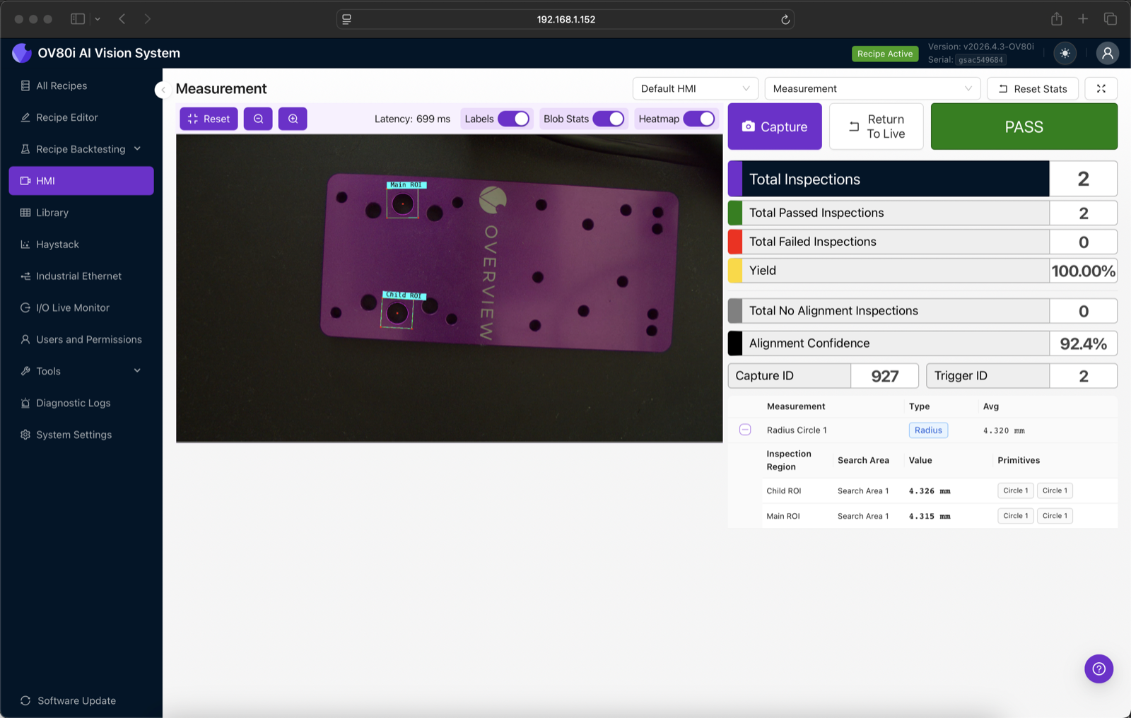
Toggle the overlays on or off as needed:
- Labels — show primitive names on the image
- Blob Stats — show detection scores
- Heatmap — overlay the model's confidence heatmap (useful for debugging "why did it pick that point?")
Working examples
Hole diameter check
- Primitive: one Circle in a Child ROI tight around the hole
- Measurement: Radius (the result is reported as radius; multiply by 2 in the Function node if you need diameter)
- Pass/fail:
Math.abs(radius - target) <= tolerance
Gap between two parts
- Primitives: two parallel Line/Segment primitives along the facing edges
- Measurement: Distance, Line-to-Line
- Pass/fail:
gap >= min_gap && gap <= max_gap
Hole-to-hole spacing
- Primitives: two Circle primitives, one in each hole
- Measurement: Distance, Point-to-Point (between the centers)
- Pass/fail:
Math.abs(spacing - target) <= tolerance
Bend angle of a bracket
- Primitives: two Line primitives, one along each arm of the bracket
- Measurement: Angle, Line-to-Line
- Pass/fail:
Math.abs(angle - target_degrees) <= angle_tolerance
Tips and tricks
Once calibration is dialed in, physically lock down the camera, lens, and part fixture. Any movement invalidates the px/mm value silently. A torque-strip on the focus ring and threadlocker on the lens mount are not overkill in a production install.
The Primitive Editor's 4x magnifier shows the pixels you're clicking on. Edge accuracy in labels is the ceiling on edge accuracy in production. Don't click "near" the edge — click on the edge, zoomed in.
Before rolling out, capture 30+ frames covering pass and fail cases and feed them through Recipe Backtesting. It runs the whole recipe against the test set in seconds and reports per-frame measurements, so you can confirm the tolerance you set in the Function node actually separates good parts from bad without false positives.
Repeating the top-of-page warning: standard C-mount lenses introduce perspective distortion that gets worse near the edges of the image and shifts with working distance. A telecentric lens is the single piece of hardware that makes dimensional inspection accurate. If your install does not have one, do not use the Measurement block.
The Measurement Block view does not autosave. Click Save Annotations after every capture or two — closing the tab loses any unsaved labels.
Common pitfalls and troubleshooting
| Symptom | Likely cause | Fix |
|---|---|---|
| Camera reads 4.3 mm, calipers read 4.5 mm | Calibration is off | Recalibrate against a longer reference dimension; verify the px/mm value didn't change |
| Same part measures differently each cycle | Alignment is unstable, or motion blur | Tighten template / search area, drop exposure, add strobe, lock the fixture |
| Predictions jump to wrong feature | Primitive labels not consistent across training captures | Re-label captures, ensure "Circle 1" is always the same physical feature, retrain |
| Model finds primitive on a defective part it shouldn't | Training set has no examples of the defect; model has not learned to refuse | Add 5+ defect captures, label them with no primitive (or with the primitive on the correct location), retrain |
| px/mm value silently changed | Lens focused, moved, or swapped | Recalibrate. Lock the lens. Don't focus during production |
| Measurements wildly off after software update | Image rotation changed, or alignment template was lost | Open Imaging Setup and confirm Image Rotation; re-capture template if needed |
| Recipe runs slow (long latency) | Too many Child ROIs, or model running in Fastest mode without enough resolution | Consolidate ROIs, or train in Accurate mode |
If you rename a primitive, move a Child ROI, add a measurement, or change the Search Area, retrain the model. The training is tied to the spatial layout you defined; changing the layout without retraining leaves the model looking in the wrong place. The Train page will flag the model as out of date when this happens.