AI-POWERED DOCS
What do you want to know?
Step 5: Setting Up Outputs
Your AI model is trained. Now decide what the camera does with each pass/fail result — and where it sends it.
There are two questions to answer:
- How is pass/fail computed? Basic mode (rules) or Advanced mode (Node-RED).
- Where does the result go? Standalone (just the camera UI), to a PLC, or to physical digital outputs.
The two questions are independent. Pick your scenario below for the exact mode + destination combination you need, then read the relevant sections in detail.
What are you trying to do?
Pick your scenario — see exactly which mode and destination you need
The page below covers everything in detail. This picker is a shortcut to the right combination for your line.
Operators read pass/fail from the screen. No PLC, no external wiring beyond power and Ethernet to a laptop or HMI.
What to do
- Configure pass/fail rules in the IO Block (Basic mode).
- Done — results show on Live Preview and saved captures.
The global pass/fail
Every capture produces a single binary result: pass or fail. Even if you have 50 regions of interest (ROIs) doing complicated analysis, it all boils down to one answer: is this part good or bad?
That single global pass/fail is what gets sent to your PLC, HMI, stack light, reject gate, or any other system. The camera computes it on every capture; what changes between Basic and Advanced mode is how you express the rules that produce it.
Pick a logic mode
Basic mode — when to use
Use Basic mode when your pass/fail rule is a simple combination of per-ROI results. Examples:
- "All ROIs must be class = 'pass' for a global pass"
- "ROI 1 and ROI 2 must both equal 'present', ROI 3 must equal 'aligned'"
- "Class confidence threshold per ROI"
If you can describe your rule in one sentence with AND / OR / threshold, Basic mode handles it. No code, no flow editor.
Set it up:
- Navigate to the IO Block in your recipe editor
- For each ROI, set the rule (e.g., class must equal "pass")
- Choose how rules combine — all must pass, or a small custom expression
- Save
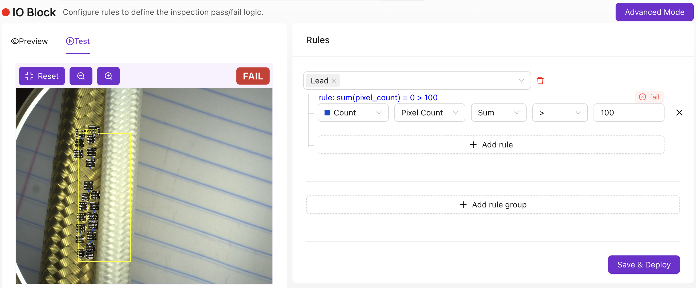
The camera now outputs pass/fail on every capture.
Basic mode produces the pass/fail signal that PLCs and the camera UI read. To drive the OV10i's physical digital output pins (DO0 / DO1) — for a stack light, reject gate, or relay — you need Advanced mode. See Digital outputs (DO0 / DO1) below.
Advanced mode — when to use
Click Advanced Mode in the IO Block to enter Node-RED, a visual programming environment.
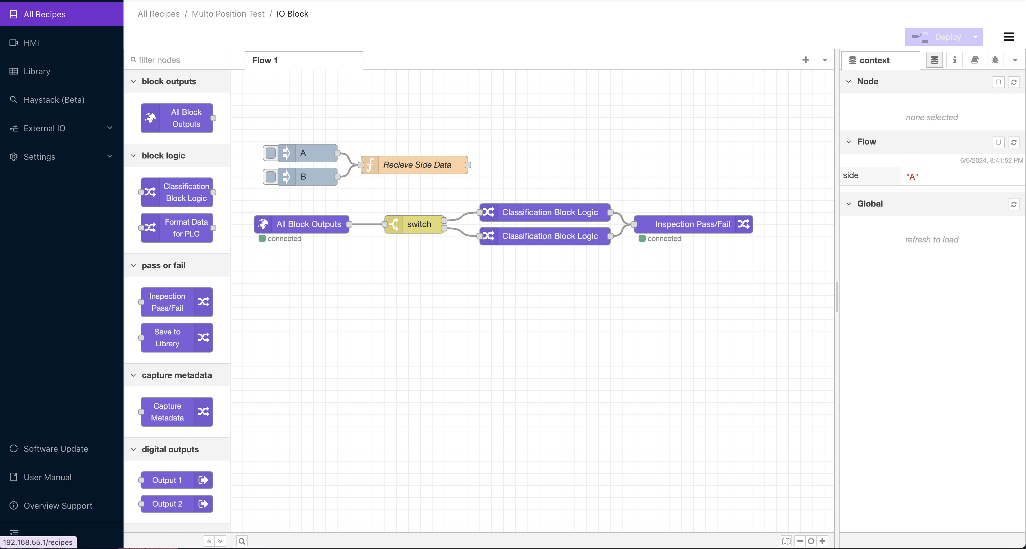
Use Advanced mode whenever:
- The pass/fail rule needs more than per-ROI thresholds — e.g., "fail if more than N ROIs are class 'fail' AND average confidence is above 80%"
- You need time-series logic — "fail if 7 of the last 10 parts failed"
- You need to drive physical digital outputs (DO0 / DO1) for a stack light, reject gate, or relay
- You need to send custom data to a PLC beyond the standard pass/fail + ROI payload (e.g., the PROFINET
User Data - 64 bytesmodule, or extra EtherNet/IP assembly fields) - You need to route data anywhere external — MQTT, MES, FTP, REST APIs, email, Teams, databases
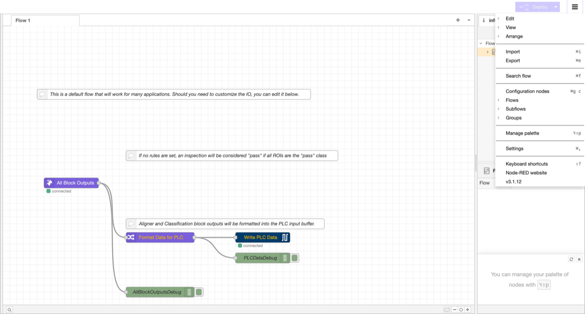
Every capture launches a new flow. The "All Blocks Output" node exposes all the metadata from the capture as a JSON object — class, confidence, ROI names, timestamps — so any downstream node can branch on any field.
Things you can build:
- Custom pass/fail logic combining multiple ROI fields
- Stack-light, reject-gate, and relay control (digital outputs)
- Time-series analysis ("Have 7 of my last 10 parts failed? Alert the supervisor")
- Custom dashboards: Pareto charts, trend visualizations, production metrics
- Data routing to FTP, MES systems, databases
- Barcode integration linking inspection results to part serial numbers
- Conditional image saving (e.g., save only on fail)
- Email / Teams / Slack notifications
- Communication protocols: RS232, RS485, MQTT, HTTP/HTTPS, OPC-UA
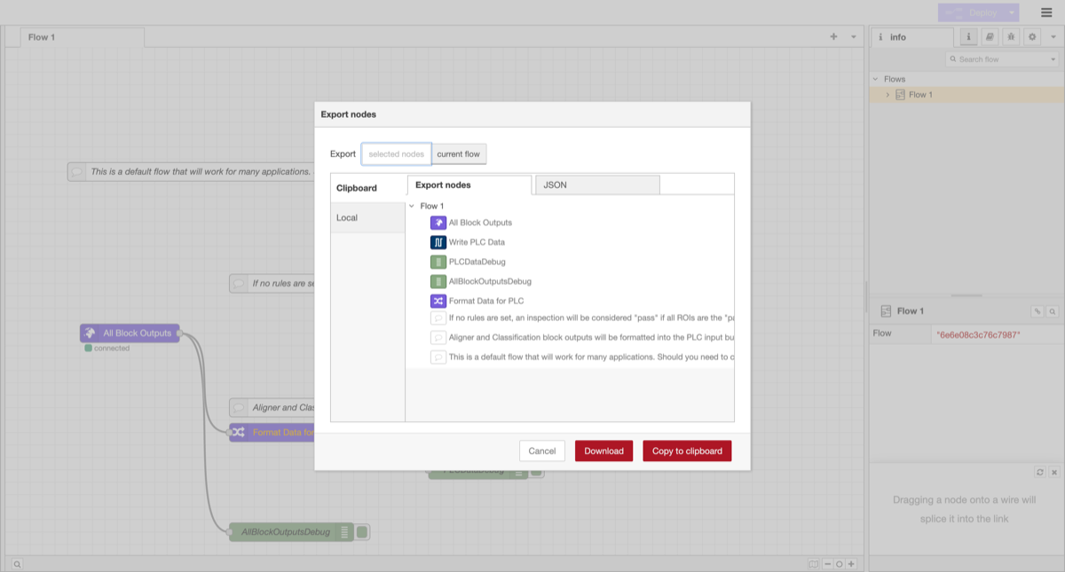
Importing and exporting flows
You can import and export Node-RED flows as JSON. This lets you back up your logic, share flows between cameras, or deploy flows generated by the Auto-Integration Builder.
To access import/export, click the hamburger menu (three horizontal lines) in the top-right corner of the Node-RED editor:
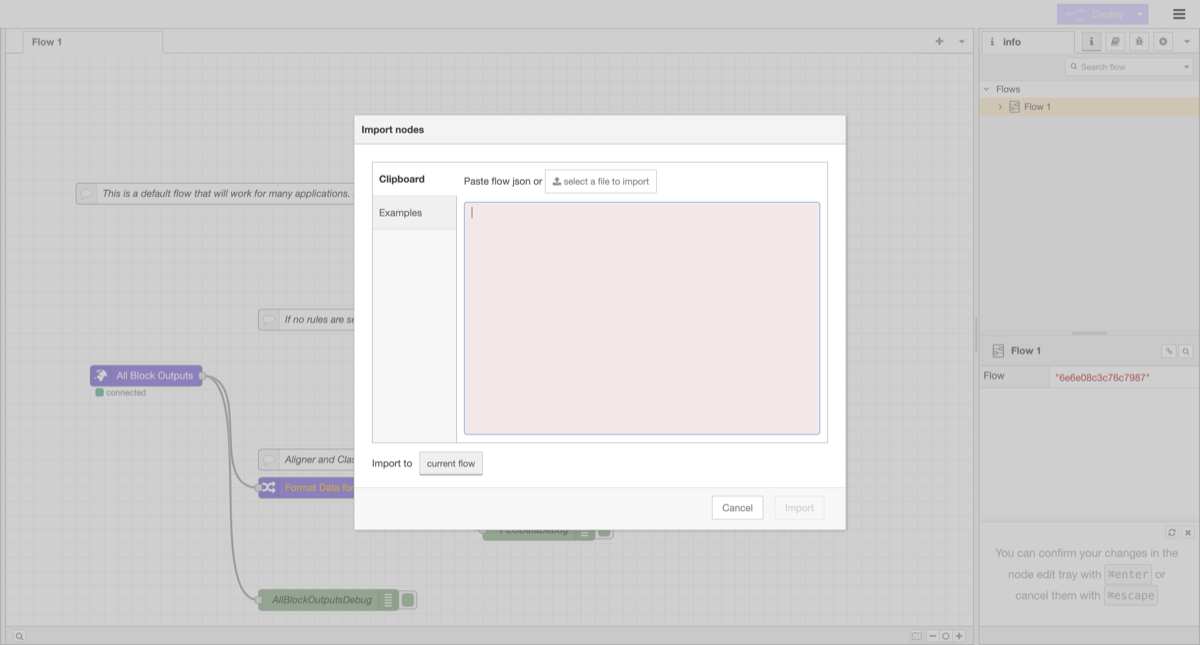
To import a flow: Select Import from the menu. Paste the flow JSON into the text area, or click "select a file to import" to upload a JSON file. Choose whether to import into the current flow or a new flow, then click Import.
To export a flow: Select Export from the menu. Choose which nodes to export (selected nodes or current flow), then click Download to save as a file or Copy to clipboard to paste elsewhere.
Build flows instantly with Auto-Integration Builder
Don't learn Node-RED from scratch. The OV Auto-Integration Builder at tools.overview.ai generates production-ready Node-RED flows from plain English descriptions.
How it works:
- Open tools.overview.ai and select Auto-Integration Builder
- Describe what you want in plain English. For example: "Send an email when 3 failures happen in a row" or "Save fail images to an FTP server with the part serial number"
- The AI generates a complete Node-RED flow using 50+ available node types
- Review the flow, deploy it to your camera with one click
Supports:
- Communication protocols: MQTT, Modbus TCP, OPC-UA, HTTP/HTTPS, RS232, RS485
- Data routing: FTP, databases, MES systems, cloud storage
- Logic: Time-series analysis, conditional branching, aggregation
- Notifications: Email, Microsoft Teams, Slack, webhooks
- Hardware I/O: Stack lights, reject gates, conveyors, PLCs
You can also use Modify Mode: paste an existing flow and describe what you want changed. The builder updates the flow while preserving your existing logic.
Even if you've never used Node-RED, the Auto-Integration Builder lets you set up complex integrations in minutes. Describe what you want, review the generated flow, and deploy.
Output destinations
You've decided how pass/fail is computed. Now decide where it goes. There are three destinations, and each has different requirements:
| Destination | Logic mode required | Use when |
|---|---|---|
| Standalone (camera UI / saved images only) | Basic or Advanced | Operators read pass/fail from the screen; no other system needs the result |
| PLC (EtherNet/IP, PROFINET) | Basic or Advanced | A PLC drives the line and needs the inspection result |
| Digital outputs (DO0 / DO1) | Advanced (Node-RED) required | A stack light, reject gate, relay, or any physical device on the I/O connector |
You can use more than one destination at the same time — e.g., send pass/fail to a PLC over EtherNet/IP and drive a stack light through DO0.
Standalone
If the camera is the whole system — no PLC, no external wiring beyond power and Ethernet to a laptop or HMI — you don't need to do anything beyond configuring the IO Block. The pass/fail result shows on the Live Preview screen and in the saved capture history. Both Basic and Advanced mode work; pick whichever matches your logic complexity.
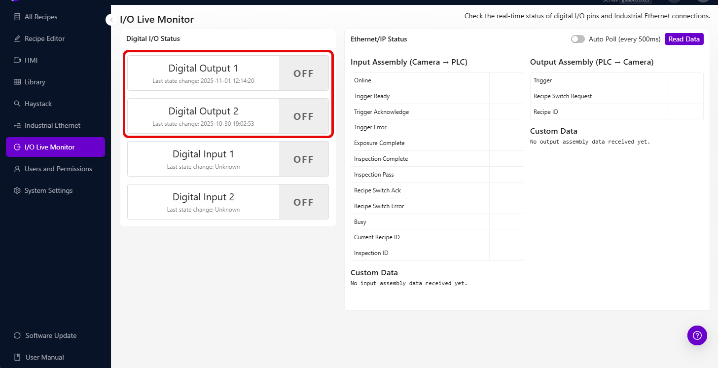
You can monitor the real-time state of digital I/O pins and EtherNet/IP connections on the I/O Live Monitor page:
PLC (EtherNet/IP and PROFINET)
The OV10i has native EtherNet/IP and PROFINET support, so the standard pass/fail + per-ROI result payload travels to your PLC without any Node-RED. You import the EDS or GSDML file, point the PLC at the camera's IP, and the camera's standard assembly / module exposes the result fields directly.
When do you need Node-RED for PLC integration? When the standard payload isn't enough — e.g., you want to send extra ROI fields, custom defect codes, computed values, or a serial number from a barcode reader. In that case:
- EtherNet/IP: extend the assembly with custom fields written from a Node-RED flow
- PROFINET: add the
User Data - 64 bytesandUser Results - 64 bytescustom modules in your TIA Portal device config and write to them from a Node-RED flow
See Connect to PLC (EtherNet/IP & PROFINET) for the wiring, files, and step-by-step setup.
Digital outputs (DO0 / DO1)
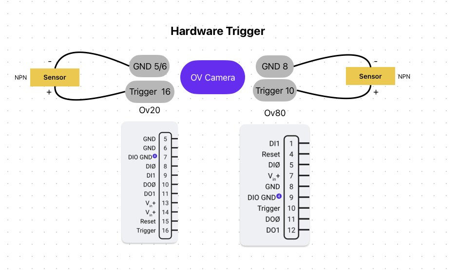
The OV10i has two digital outputs on the M12 connector — DO0 (pin 10, violet) and DO1 (pin 11, orange) — each NPN sinking, rated 100 mA per line. Use them to drive stack lights, reject gates, relays, indicator LEDs, or anything triggered by a 24V sinking signal.
There is no native "send pass to DO0" toggle in Basic mode. To turn a pin on or off based on the inspection result, you need an Advanced mode Node-RED flow with a Digital Output node wired to the inspection result. This is the same flow that handles your custom logic, so if you're already in Advanced mode for any reason, driving the DO pins is just one more node.
The simplest "pass-lights-green, fail-lights-red" flow uses two Digital Output nodes wired to the pass/fail branch. For step-by-step wiring + Node-RED setup, see Set Digital Output Logic.
Once the pins are wired and a flow is in place, you can encode richer signals than just pass/fail — different defect classes can map to different pin combinations, or you can pulse a pin for N milliseconds to drive a one-shot reject solenoid.
Incorrect wiring on the I/O board can damage the camera, connected equipment, or both. Always verify your wiring with a multimeter and run a bench test before connecting to live production hardware.
Trigger modes
Configure how captures happen:
| Trigger | Description | Best for |
|---|---|---|
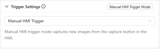
| Manual | Button press on the camera UI | Testing and setup |
| Hardware (digital input) | Electrical signal from a sensor | Automated lines with proximity sensors |
| PLC | Command from your industrial controller | Fully automated with precise timing |
| Aligner | Auto-triggers when part alignment is detected | When parts arrive at unpredictable times |
| Interval | Captures at set time intervals | Continuous monitoring |
The OV10i digital outputs have a maximum current rating. Check the hardware specifications before connecting high-power devices such as solenoids, motors, or large relays. Use an intermediate relay or driver circuit if the load exceeds the rated output current.
Deploy
- Activate the recipe
- Set your trigger mode
- Run test parts and verify the pass/fail output matches expectations
- Check edge cases, especially the hardest parts to classify
- Monitor for the first hour to ensure consistency
Download PLC integration files
If you're integrating with a PLC, download the configuration files and sample code:
EtherNet/IP (Allen-Bradley)
| File | Description |
|---|---|
| OV10i EDS File | Electronic Data Sheet for Studio 5000 (ControlLogix/CompactLogix) |
| Recipe Switch Routine | Ladder logic for changing recipes via PLC |
| Camera Trigger Routine | Ladder logic for triggering inspections and handling results |
PROFINET (Siemens)
| File | Description |
|---|---|
| OV10i GSDML File | Device description for TIA Portal |
The OV10i uses the same PLC integration interface as the OV20i. These configuration files are compatible with both cameras.
Import the EDS or GSDML file into your PLC programming environment before configuring the connection. The L5X routines are ready-to-use ladder logic that you can import directly into Studio 5000.
Output checklist
Before going live, confirm:
- IO rules configured (pass/fail logic matches your requirements)
- Trigger mode set (manual, hardware, PLC, aligner, or interval)
- Recipe activated
- Test parts run through (pass/fail output matches expectations)
- Edge cases tested (hardest parts classified correctly)
Your AI inspection is now live. For ongoing optimization, see Improving Your Model.