AI-POWERED DOCS
What do you want to know?
Install the OV10i
You've opened the box. Let's get the camera physically set up and ready to go.
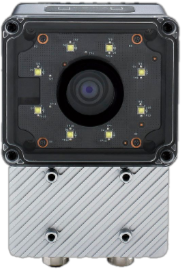
OV10i
What's in the box
Your shipment includes:
OV10i Camera
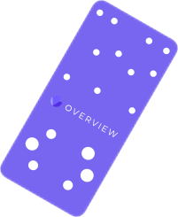
Mounting Plate

M12 Power Cable

M12 Ethernet Cable

Power Adapter
Terminal Block
| Item | What it's for |
|---|---|
| OV10i camera | The camera unit itself |
| Mounting plate + hardware | Secures the camera to your fixture |
| M12 power cable | Connects camera to 24V DC power |
| M12 Ethernet cable | Connects camera to your network/computer |
| Power adapter (if included) | Provides 24V DC power |
| Lens (may be pre-installed) | Captures the image |
You'll find two M12 cables in the box: one for power, one for Ethernet. You need both connected for the camera to work. The power cable has a 17-pin M12 A-coded connector. The Ethernet cable is standard M12 D-coded.
Choosing the right lens
Lens selection is typically handled by your Sales or Applications Engineer before deployment. The information below is provided for reference if needed.
The lens determines what the camera sees and how much detail it captures. This choice directly impacts everything downstream.
The goal: Fill the frame with your part as much as possible. If the part only occupies a small portion of the image, you're wasting pixels, and pixels are your resolution.
| Lens type | Best for | Watch out for |
|---|---|---|
| Short focal length (4-6mm) | Large parts, short working distance | More distortion at edges (barrel/fisheye effect) |
| Medium focal length (8-12mm) | Most applications | Good balance of field of view and distortion |
| Long focal length (16mm+) | Small parts, long working distance | Narrower field of view |
The OV10i comes with built-in S-mount lenses and software-controlled motorized focus. You can adjust focus from the browser UI without physically touching the camera.
If you use a wide-angle lens (short focal length), the image will have barrel distortion. Straight lines appear curved, especially at the edges. This directly impacts alignment accuracy later. You can correct it in software (lens distortion correction), but you need to know your lens causes distortion. We'll cover this in the image settings step.
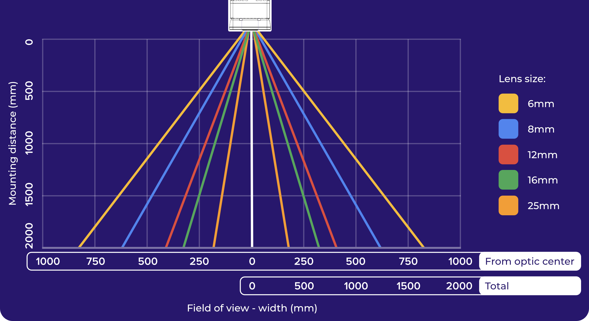
Use the Optics Calculator to determine your exact field of view, recommended mounting distance, and minimum detectable defect size before installing the camera. Getting optics right at this stage prevents costly rework later.
Setting up your lighting
Lighting requirements are typically determined by your Sales or Applications Engineer as part of the system design. The information below is provided for reference if needed.
Lighting is a physical problem that cannot be solved in software. The AI can only work with what the camera sees, and what the camera sees depends entirely on how the part is lit.
Good lighting means:
- Uniform: no bright spots or dark shadows across the part
- Repeatable: the same lighting every time (avoid ambient light changes from windows, overhead lights cycling, day/night variation)
- Reveals your defects: if you're looking for scratches, angled lighting makes them visible. If you're looking for color differences, even diffuse lighting works best
The OV10i has built-in LED lighting with adjustable intensity and patterns. You can configure these in software later. The built-in LEDs work well for close-range inspections. For longer working distances or large parts, you may still need external lighting.
Common lighting mistakes:
- Relying on factory overhead lights (they change throughout the day)
- Creating glare on shiny or reflective surfaces
- Under-lighting so the image is dark and noisy
Step 1: Mount the camera
This is more important than it sounds. The camera must be mounted stably and must not move. Any vibration or shifting will undermine everything that follows: alignment, inspection accuracy, AI training, all of it.
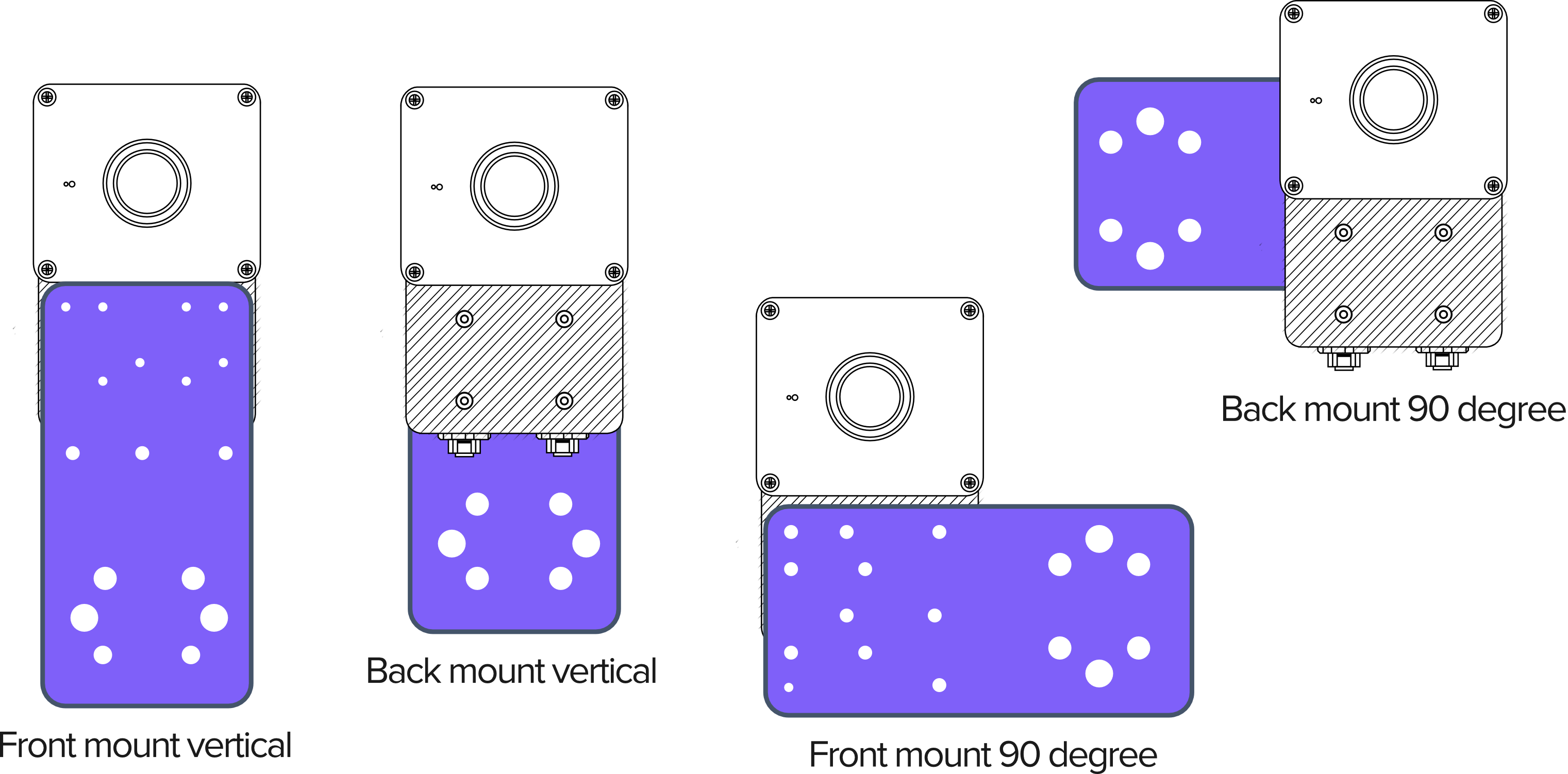
- Use the mounting plate and brackets provided
- Tighten all fasteners fully
- If mounting on a machine frame, check for vibration. A camera that shakes even slightly will produce inconsistent results
- Consider the angle: mount the camera so it looks straight down (or straight at) the part
A camera that moves even 1-2 pixels between captures will cause alignment drift and AI accuracy issues that are very hard to diagnose later. Spend the extra minute here to make sure the mount is rock-solid.
Mounting dimensions and 2D drawings
Use the dimensioned drawing below for mounting hole locations, spacing, and clearance planning. These dimensions are critical for designing custom mounting plates or brackets.
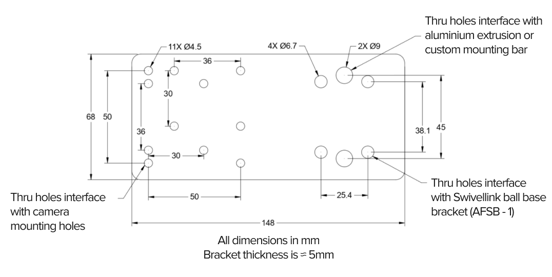
OV10i mounting plate 2D dimensioned drawing
Step 2: Connect the cables
M12 17-pin power (OV10i)

M12 to RJ45 Ethernet
- Power cable: Connect the M12 power cable between the camera and your 24V DC power source (19-24 VDC, minimum 1A supply; camera draws up to 18W (typically 15W))
- Ethernet cable: Connect the M12 Ethernet cable between the camera and your computer, switch, or network
Both cables must be connected. The camera needs power to run and Ethernet to communicate.
The OV10i has female M12 connectors on the camera body for both power and Ethernet. Your cables need male M12 ends on the camera side.
- Voltage: 19-24 VDC regulated
- Current: Minimum 1A
- Power: Typical 15W, max 18W
- Pins 13 or 14 = 24V DC (+), Pins 5 or 6 = GND
- Do not use unregulated power supplies; voltage spikes can damage the camera
Step 3: Power up and verify
Once both cables are connected:
- Apply power
- Watch the LEDs on top of the camera:
- Power LED turns solid green: power is good
- System Status LED blinks slowly during boot, then turns solid: system is ready
- Boot takes approximately 30 seconds
- If LEDs don't light up, check your power connections and voltage
| LED state | Meaning |
|---|---|
| Power LED solid green | Power OK |
| Power LED off | No power; check cables and supply |
| System LED slow blink | Booting up; wait 30 seconds |
| System LED solid | Camera ready |
| System LED fast blink | Error; check connections |
All four LEDs are located on the top of the OV10i.
Download 3D CAD models
Desktop required for CAD downloads
3D CAD models (.STEP, .SLDPRT) are available for download when viewing on a desktop computer. These files require CAD software to open.
Download 3D models for integration planning, fixture design, or mounting layout:
| File | Format | Description |
|---|---|---|
| Mounting Plate | STEP | Mounting plate for bracket integration |
| OV10i Camera Body | STEP | Full camera body for layout planning |
| OV10i Camera Body | SolidWorks | Native SolidWorks part file |
The OV10i shares the same physical enclosure and mounting plate as the OV20i. These CAD models are compatible with both cameras.
These models include all external dimensions, mounting holes, and connector positions. Import them into your CAD software to verify clearances before installation.
Install checklist
Before moving on, confirm:
- Camera is mounted stably (give it a shake test; it shouldn't budge)
- Lens is appropriate for your working distance and part size
- Lighting is set up and consistent
- Power cable connected, Power LED is green
- Ethernet cable connected
- System LED is solid after boot
All green? Head to Open the OV10i in Your Browser.