AI-POWERED DOCS
What do you want to know?
Digital I/O Logic: NPN vs PNP
This page explains the OV80i's digital I/O configuration and how to properly wire NPN and PNP devices to the camera's M12 A-Coded 12 Pin connector.
OV80i Digital I/O Overview
Hardware Configuration
The OV80i provides 1 trigger input, 2 digital inputs, and 2 digital outputs through the M12 A-Coded 12 Pin Power I/O connector:
I/O Distribution:
- 1 Trigger Input - Primary trigger signal input
- 2 Digital Inputs - Additional sensor inputs
- 1 Digital Outputs - Result outputs
Electrical Specifications
- Operating Voltage: 19-24 VDC input
- Output Current: Max 100mA per output
- Input Logic: Pull to GND to activate input
- Output Logic: When active, output sinks to GND (NPN-compatible)
- Thermal Protection: DIO GND tied through thermal fuse
Understanding NPN vs PNP Logic
NPN (Sinking) Logic
NPN devices sink current to ground when active.
Characteristics:
- Active State: Device connects signal to GND (0V)
- Inactive State: Signal remains floating or pulled high
- Current Flow: From positive supply → through load → to device → to ground
- Common Use: Most modern industrial sensors and PLCs
PNP (Sourcing) Logic
PNP devices source current from positive supply when active.
Characteristics:
- Active State: Device connects signal to positive supply (+24V)
- Inactive State: Signal remains floating or pulled low
- Current Flow: From device → through load → to ground
- Common Use: Some European industrial equipment
OV80i Digital Input Configuration
Native Input Logic: NPN Compatible
The OV80i inputs are designed for NPN (sinking) devices.
Input Activation: Pull to GND to activate input
Connecting NPN Sensors (Direct Connection)
Wiring for NPN Sensors:
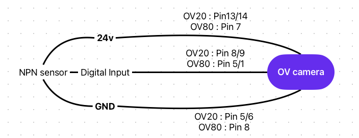
Operation:
- Sensor Inactive: Input floats high (inactive)
- Sensor Active: Sensor pulls input to GND (active)
Connecting PNP Sensors (Pull-Down Required)
Pull-Down Resistor: Typically 10kΩ between input and GND
Operation:
- Sensor Inactive: Pull-down resistor holds input at GND (inactive)
- Sensor Active: Sensor overpowers pull-down, raising input voltage (may not activate reliably)
PNP sensors require additional interface circuitry for reliable operation with OV80i inputs.
OV80i Digital Output Configuration
Native Output Logic: NPN (Sinking)
The OV80i outputs are NPN-compatible sinking outputs.
Output Behavior:
- Active: Output sinks to GND (0V)
- Inactive: Output floating (high impedance)
- Max Current: 100mA per output
- External Power Required: Outputs require external power supply
Digital outputs DO0 / DO1 are NPN open-collector, sinking only. They pull the line to GND when active and cannot source +24 V. An external pull-up or load to +24 V must be provided for proper operation.
Wiring for PNP Loads (Interface Required):
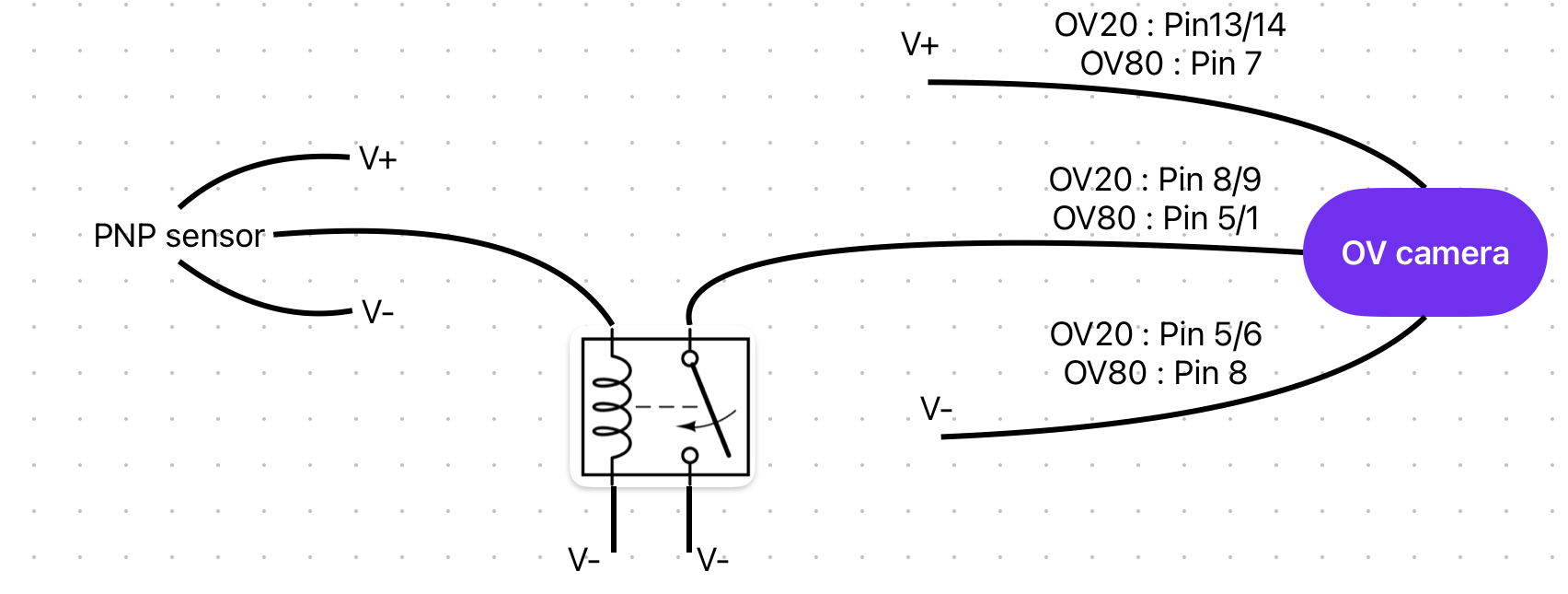
Interface Options:
- Relay Module: Use output to drive relay coil, relay contacts switch PNP load
- Transistor Circuit: Use output to control PNP transistor for load switching
Grounding and Common Reference
Critical Grounding Requirements
DIO GND must be connected to GND for digital input functionality to work. DIO GND is tied to GND through a thermal fuse.
Multi-Supply Systems: When connecting the OV80i's digital I/O lines to a system that is powered from a different power supply, use this pin to tie the grounds together.
⚠️ Common Wiring Issues
Ground Loop Problems
- Symptom: Erratic input behavior, false triggers
- Solution: Ensure single-point grounding, use DIO GND properly
Insufficient Output Current
- Symptom: Loads don't activate reliably
- Solution: Verify load current < 100mA, use relay for higher current loads
PNP Sensor Incompatibility
- Symptom: Inputs don't respond to PNP sensors
- Solution: Add pull-down resistors or use interface modules
Floating Inputs
- Symptom: Random triggering when no sensor connected
- Solution: Connect unused inputs to DIO GND through 10kΩ resistor
Best Practices
Design Guidelines
- ✅ Use NPN devices when possible for direct compatibility
- ✅ Verify ground connections before applying power
- ✅ Add protection (fuses/surge suppressors) for industrial environments
- ✅ Document wiring for maintenance and troubleshooting
Testing Procedures
- Verify supply voltages (19-24 VDC)
- Check continuity of ground connections
- Test inputs with multimeter before connecting sensors
- Validate outputs with appropriate loads
- Monitor current draw to ensure < 100mA per output
Need to build custom logic around your digital I/O signals? The Integration Builder can generate Node-RED flows that combine digital I/O with inspection results, timers, and conditional logic from a plain English description.