AI 驱动文档
您想了解什么?
数字 I/O 逻辑:NPN 与 PNP
本页面解释了 OV80i 的数字 I/O 配置,以及如何正确连接 NPN 和 PNP 设备到相机的 M12 A 型 12 针连接器。
OV80i 数字 I/O 概述
硬件配置
OV80i 通过 M12 A 型 12 针电源 I/O 连接器提供 1 个触发输入、2 个数字输入和 2 个数字输出:
I/O 分配:
- 1 个触发输入 - 主要触发信号输入
- 2 个数字输入 - 额外传感器输入
- 1 个数字输出 - 结果输出
电气规格
- 工作电压: 19-24 VDC 输入
- 输出电流: 每个输出最大 100mA
- 输入逻辑: 拉至 GND 以激活输入
- 输出逻辑: 激活时,输出接地(兼容 NPN)
- 热保护: DIO GND 通过热熔断器连接
理解 NPN 与 PNP 逻辑
NPN(下拉)逻辑
NPN 设备在激活时将电流引至地。
特性:
- 激活状态: 设备将信号连接至 GND(0V)
- 非激活状态: 信号保持浮动或拉高
- 电流流动: 从正电源 → 通过负载 → 到设备 → 到地
- 常见用途: 大多数现代工业传感器和 PLC
PNP(上拉)逻辑
PNP 设备在激活时从正电源引出电流。
特性:
- 激活状态: 设备将信号连接至正电源(+24V)
- 非激活状态: 信号保持浮动或拉低
- 电流流动: 从设备 → 通过负载 → 到地
- 常见用途: 一些欧洲工业设备
OV80i 数字输入配置
原生输入逻辑:兼容 NPN
OV80i 输入设计为 NPN(下拉)设备。
输入激活: 拉至 GND 以激活输入
连接 NPN 传感器(直接连接)
NPN 传感器接线:
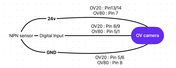
操作:
- 传感器非激活: 输入浮动高(非激活)
- 传感器激活: 传感器将输入拉至 GND(激活)
连接 PNP 传感器(需要下拉电阻)
下拉电阻: 通常为 10kΩ,连接输入与 GND
操作:
- 传感器非激活: 下拉电阻将输入保持在 GND(非激活)
- 传感器激活: 传感器克服下拉电阻,提高输入电压(可能无法可靠激活)
重要
PNP 传感器需要额外的接口电路以确保与 OV80i 输入的可靠操作。
OV80i 数字输出配置
原生输出逻辑:NPN(下拉)
OV80i 输出为 NPN 兼容的下拉输出。
输出行为:
- 激活: 输出接地(0V)
- 非激活: 输出浮动(高阻抗)
- 最大电流: 每个输出 100mA
- 需要外部电源: 输出需要外部电源供电
注意
数字输出 DO0 / DO1 为 NPN 开路集电极,仅下拉。它们在激活时将线路拉至 GND,无法提供 +24 V。必须提供外部上拉或负载至 +24 V 以确保正常操作。
PNP 负载接线(需要接口):
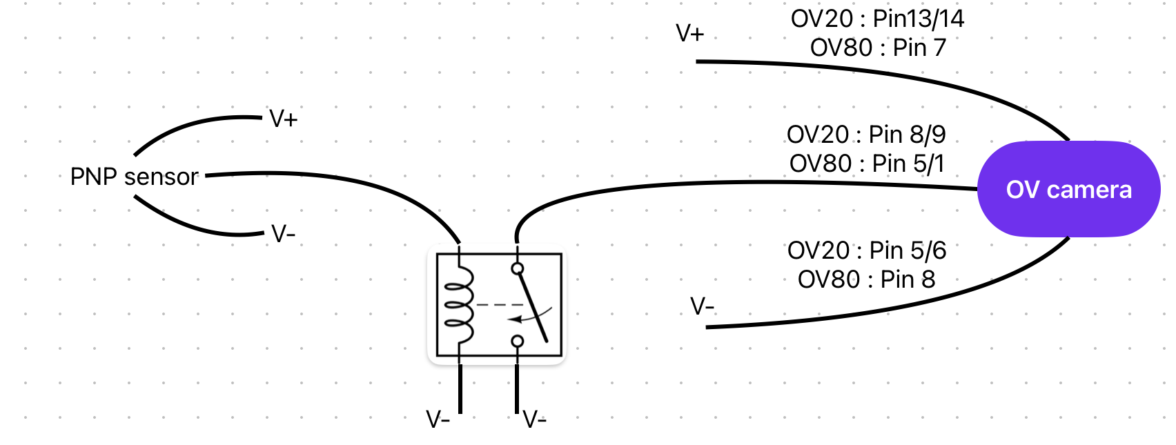
接口选项:
- 继电器模块: 使用输出驱动继电器线圈,继电器触点切换 PNP 负载
- 晶体管电路: 使用输出控制 PNP 晶体管进行负载切换
接地和公共参考
关键接地要求
DIO GND 必须连接到 GND,以使数字输入功能正常工作。 DIO GND 通过热熔断器与 GND 相连。
多电源系统: 当将 OV80i 的数字 I/O 线路连接到来自不同电源的系统时,请使用此引脚将接地连接在一起。
⚠️ 常见接线问题
接地环路问题
- 症状: 输入行为不稳定,误触发
- 解决方案: 确保单点接地,正确使用 DIO GND
输出电流不足
- 症状: 负载无法可靠激活
- 解决方案: 验证负载电流 <100mA,使用继电器处理更高电流负载
PNP 传感器不兼容
- 症状: 输入对 PNP 传感器没有响应
- 解决方案: 添加下拉电阻或使用接口模块
漂浮输入
- 症状: 未连接传感器时随机触发
- 解决方案: 通过 10kΩ 电阻将未使用的输入连接到 DIO GND
最佳实践
设计指南
- ✅ 尽可能使用 NPN 设备 以实现直接兼容
- ✅ 在通电前验证接地连接
- ✅ 为工业环境添加保护(熔断器/浪涌抑制器)
- ✅ 记录接线 以便于维护和故障排除
测试程序
- 验证供电电压(19-24 VDC)
- 检查接地连接的连续性
- 在连接传感器之前用万用表测试输入
- 用适当的负载验证输出
- 监测电流消耗 以确保每个输出 <100mA
使用 Node-RED 自动化 I/O 逻辑
需要围绕您的数字 I/O 信号构建自定义逻辑吗?集成构建器 可以生成将数字 I/O 与检测结果、定时器和基于自然语言描述的条件逻辑相结合的 Node-RED 流。