AI-POWERED DOCS
What do you want to know?
LED Behavior Matrix
This page explains the behavior and purpose of each LED indicator on the OV80i camera, based on color and function.
note
Use this as a quick visual reference during setup, inspection, and troubleshooting.
LED Locations & Meanings
The OV80i includes 4 LED indicators on the top panel of the device, each with a distinct purpose:
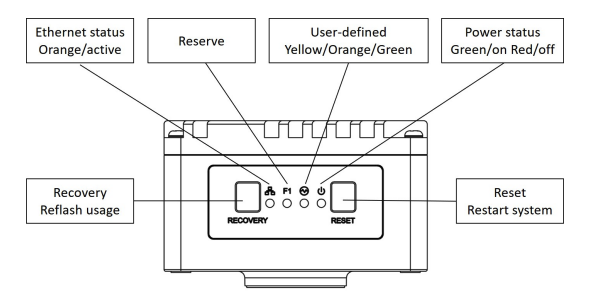
| LED Label | Color | Function |
|---|---|---|
| Ethernet Status | 🟠 Orange (Active) | Indicates network link or activity |
| Reserve | (Off) | Reserved for future use |
| User-defined | 🟡/🟠/🟢 Yellow, Orange, Green | Reserved for software-defined behaviors |
| Power Status | 🟢 Green (On) / 🔴 Red (Fault) | Indicates system power and health status |
Button Functions
| Button | Function | Notes |
|---|---|---|
| Recovery | Reflash usage | Only use if instructed by support |
| Reset | Restart system | Safe reboot |
LED Quick Reference Table
| LED | State | What It Means |
|---|---|---|
| Ethernet (🟠) | Solid or blinking | Network link present and active |
| Power (🟢/🔴) | Green = On | System is powered and operational |
| Red = Fault | Power fault detected (check power input) |
Field Usage Notes
- Ethernet LED not lit? → Check cable seating, switch status, or static IP conflict
- Power LED is Red? → Confirm 19-24 VDC input and M12 connector seating
- User-defined LED has an unexpected color? → Check the logic in your Node-RED flow.