AI-POWERED DOCS
What do you want to know?
I/O Timing Diagrams
This page details digital I/O timing specifications for the OV10i, including trigger signal timing, output latency, and recommended pulse widths.
Digital Input Timing
Trigger Input Timing (Pin 16)
| Parameter | Spec |
|---|---|
| Input Activation Type | NPN (Pull to GND) |
| Minimum Pulse Width | 10 ms |
| Input Debounce | ~5 ms |
| Max Input Frequency | ~20 Hz |
| Signal Type | Dry contact or open collector |
Trigger fires once per pulse
Ideal for sensors with clean output transitions
Digital Output Timing
Result Output Timing (Pins 10 & 11)
| Event | Timing |
|---|---|
| Output Activation Delay | ~10–15 ms after inference |
| Output Active Duration | Configurable (default 100 ms) |
| Max Current | 100 mA |
| Output Logic Type | NPN open collector (pulls to GND) |
warning
Digital outputs are NPN open-collector, sinking only. They pull the line to GND when active and cannot source +24 V. An external pull-up or load to +24 V must be provided for proper operation.
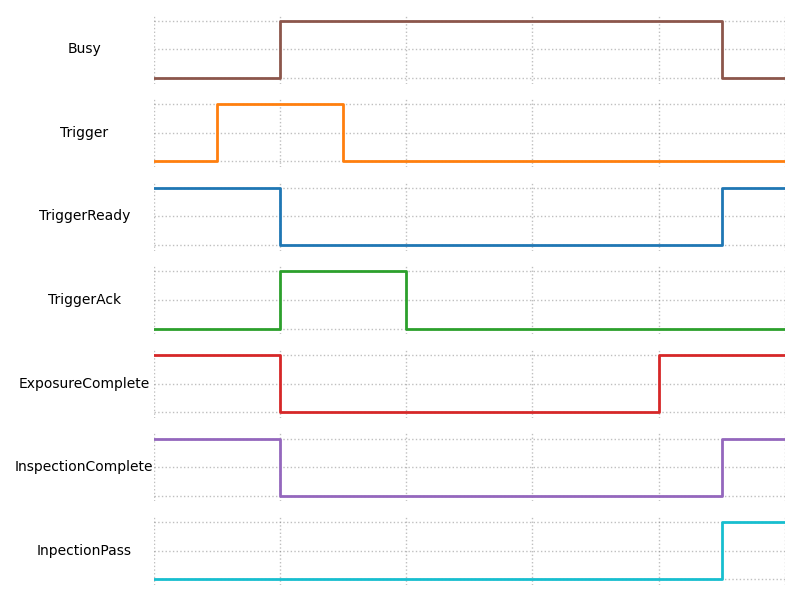
Typical Timing Sequence (Digital Trigger)
CopyEdit
     Trigger Pulse
         ___
        |   |____________________
        |
        |<-- 10 ms -->|

     Inference Timing (AI Process)
                      _______________________
                     /
    Result Output __/

        |<-- ~10–15 ms after trigger -->|
Recommended Setup
- Trigger via dry contact, NPN sensor, or PLC sinking output
- Set minimum pulse width: 10–20 ms
- Configure output duration via UI or PLC tag if required
Best Practices
- Use shielded cables to minimize noise
- Confirm rising/falling edge behavior matches PLC expectations
- Check output with a test light or multimeter during setup
- Avoid signal bounce by using sensors with built-in debounce