DOCUMENTACIÓN CON IA
¿Qué desea saber?
Múltiples Vistas en una Sola Receta
Esta guía le muestra cómo configurar una sola receta que pueda inspeccionar diferentes piezas, ángulos o vistas sin tener que cambiar a otras recetas. Hay diversas razones para hacer esto, pero los dos casos de uso principales son:
- cuando no hay tiempo suficiente entre capturas para cambiar de receta,
- cuando se realiza la misma inspección en múltiples piezas o ángulos de una pieza (por ejemplo, presencia/ausencia de pernos en cinco posiciones diferentes en una carrocería de auto). En este caso, este método evita tener que entrenar el mismo modelo (presencia/ausencia de pernos) varias veces en diferentes recetas.
El siguiente ejemplo es una versión simple con dos vistas y un tipo de inspección, pero puede usar esta misma técnica para una cantidad ilimitada de tipos de inspección y vistas. En esta inspección, buscaremos la presencia/ausencia de brocas en dos lados de un estuche de brocas. Un lado tiene cinco brocas en la parte inferior, y el otro lado tiene ocho brocas tanto en la parte superior como en la inferior. Llamaremos al lado con 16 brocas, lado A, y al de cinco brocas, lado B.
 |  |
|---|---|
| Lado A (16 brocas) | Lado B (5 brocas) |
Crear y Entrenar una Nueva Receta
En lugar de una receta por lado, debido a los diferentes layouts, combinaremos ambos lados en una sola receta para no tener que entrenar el mismo modelo de presencia/ausencia dos veces.
-
Cree una nueva receta. En este caso, es una receta de clasificación, pero este mismo principio se puede usar con segmentación.
-
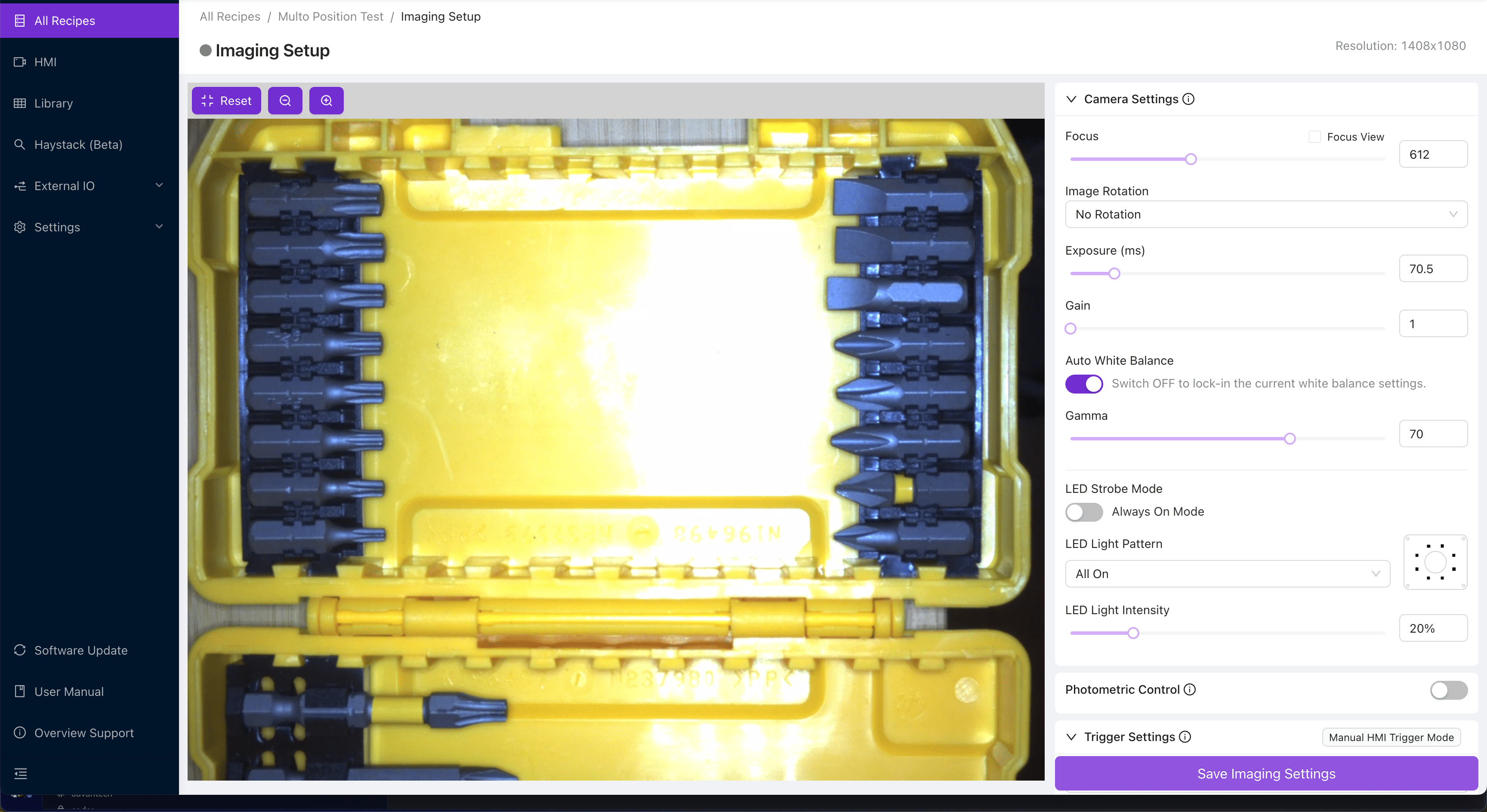
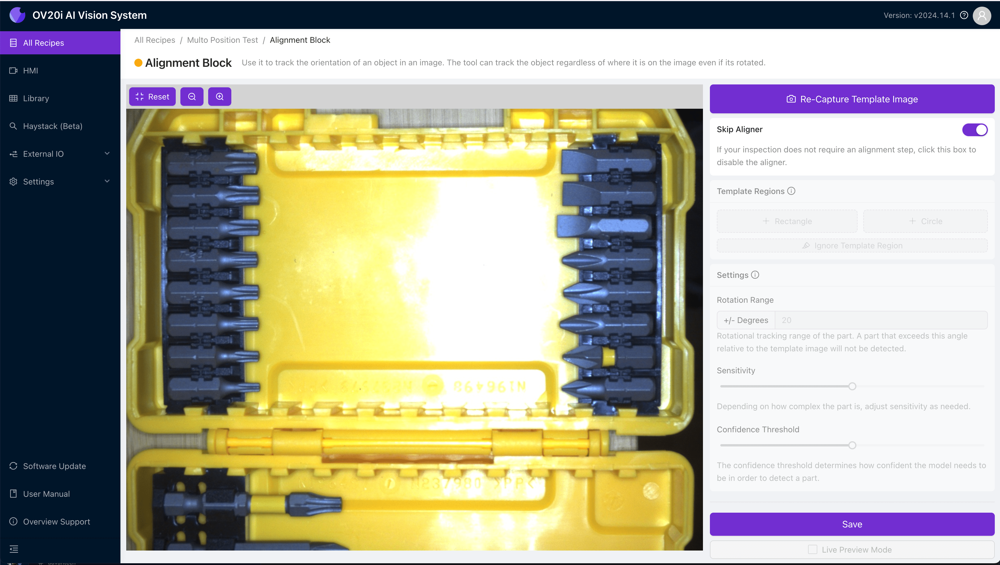
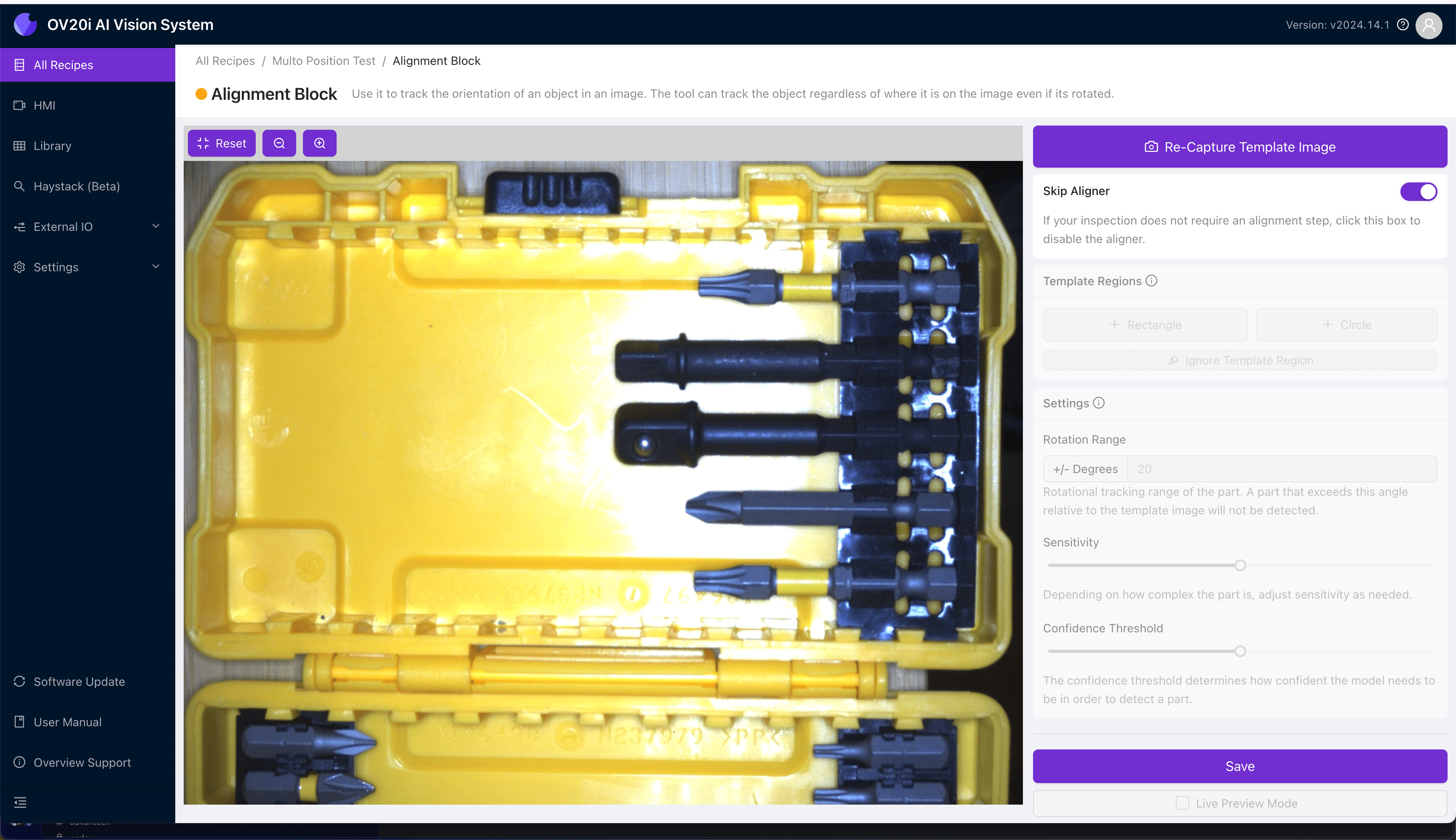
Configure la imagen de plantilla y la alineación para la primera vista:
El alineador no está disponible al inspeccionar más de una vista en la misma receta. La imagen de plantilla y el alineador solo se usan para establecer la imagen base para la configuración de inspección.
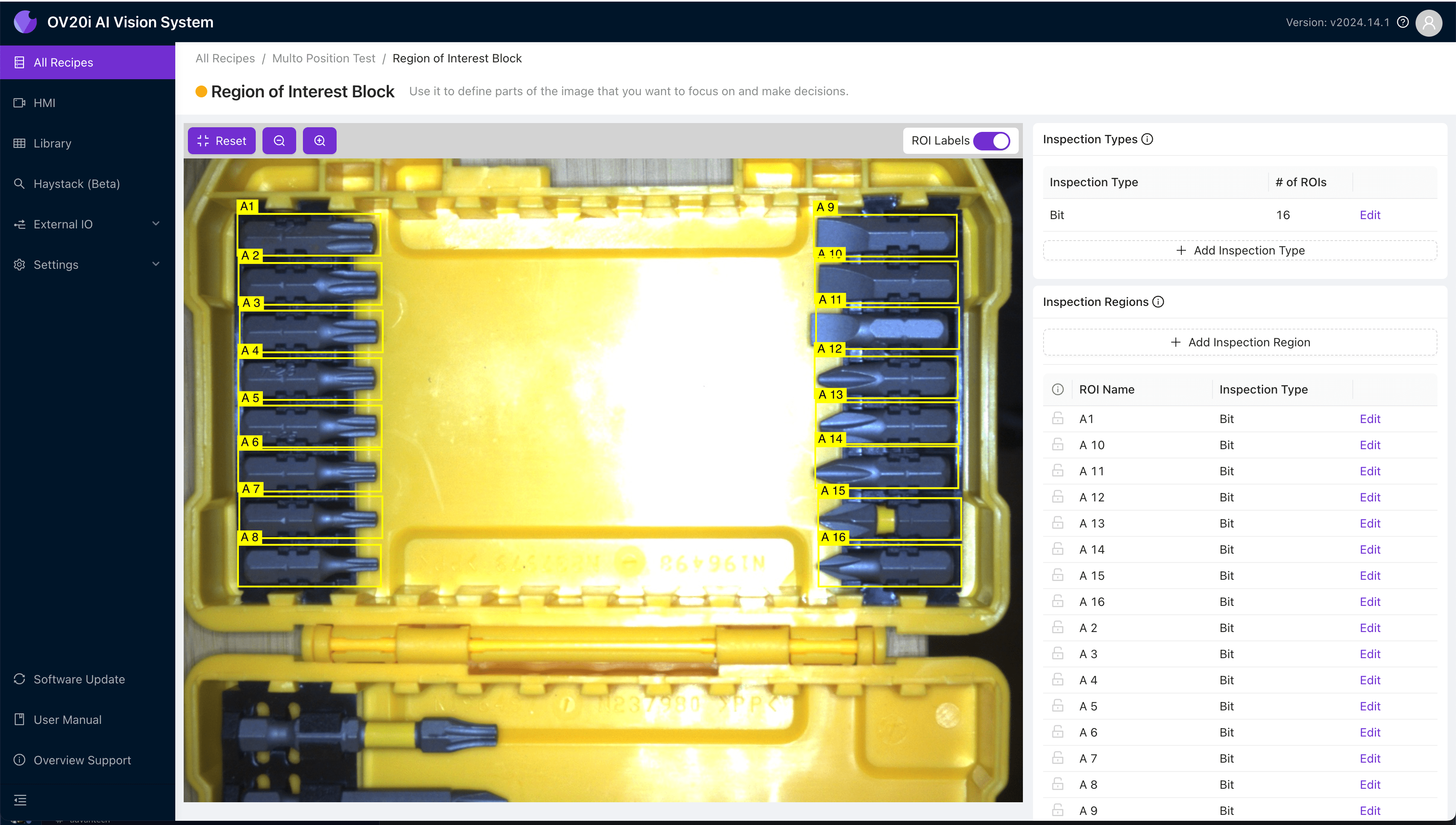
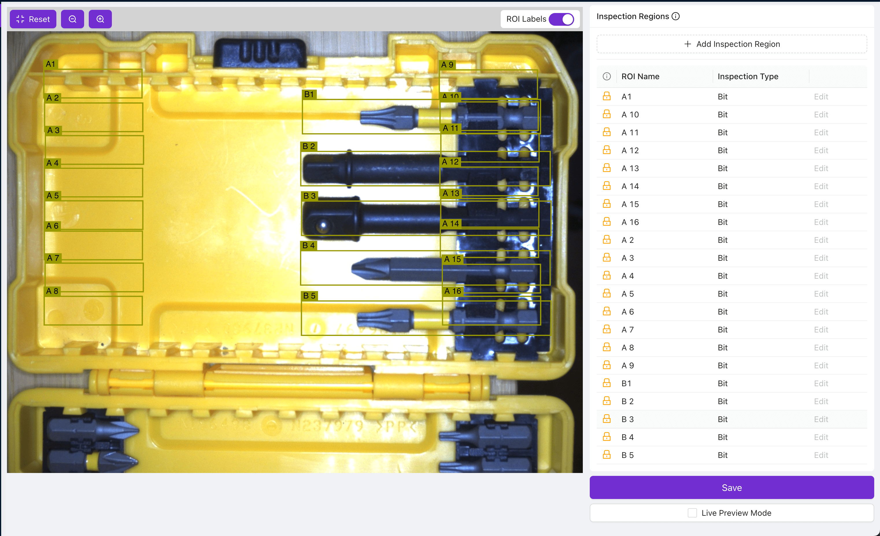
- Dibuje los ROIs para el lado A. Nómbrelos de manera que ayude a identificar a qué lado pertenecen. En este caso, nombramos los ROIs como A1-A16.
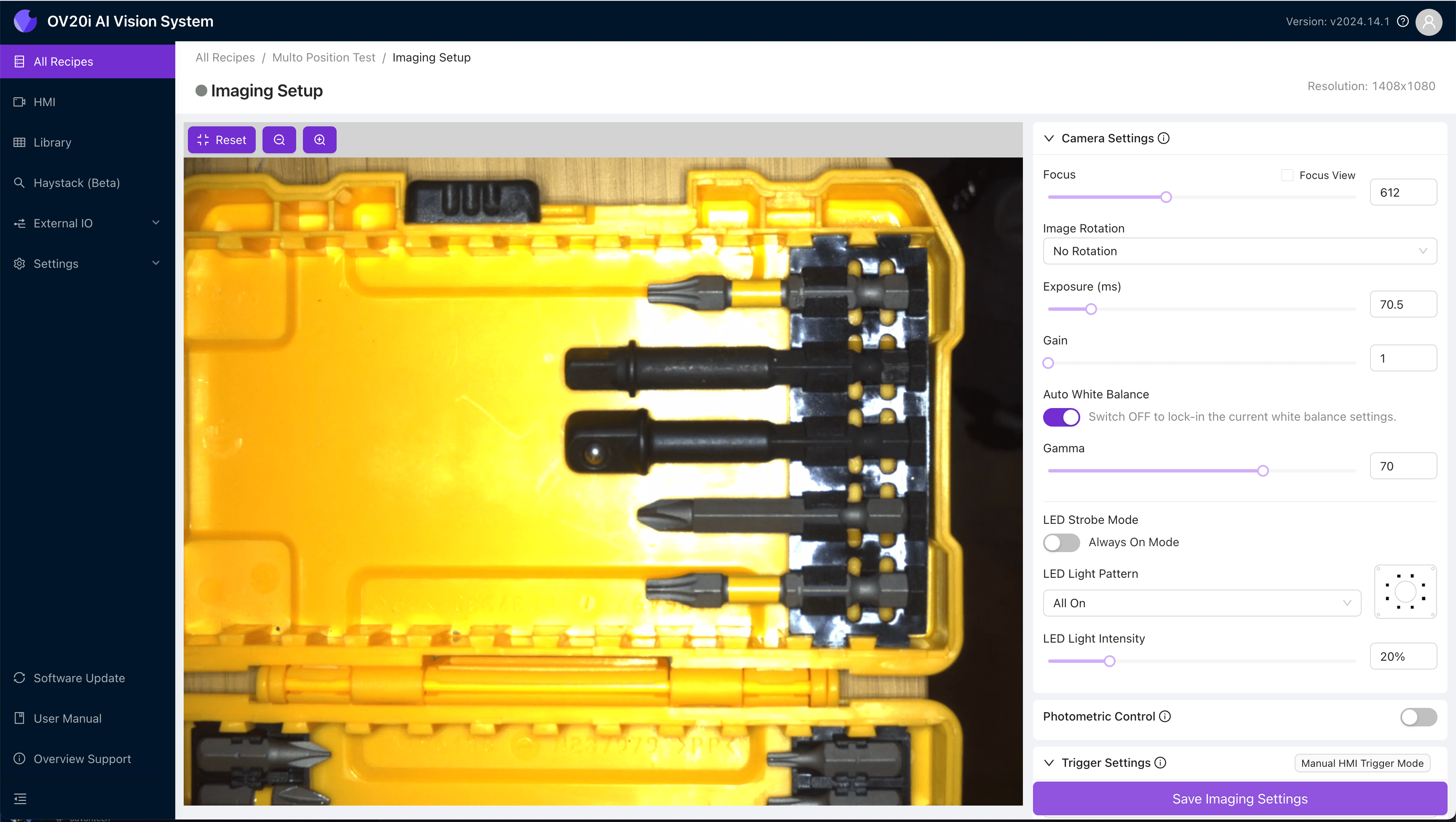
- Regrese a la imagen de plantilla y alineación para reemplazar la imagen con el lado B, ya sea desde una nueva captura o desde la Biblioteca.
- Use los iconos de candado junto a cada ROI para evitar mover los ROIs del lado A, luego dibuje y nombre los ROIs para el lado B.
Para recetas más complejas, repita este proceso para tantas vistas diferentes como desee inspeccionar.
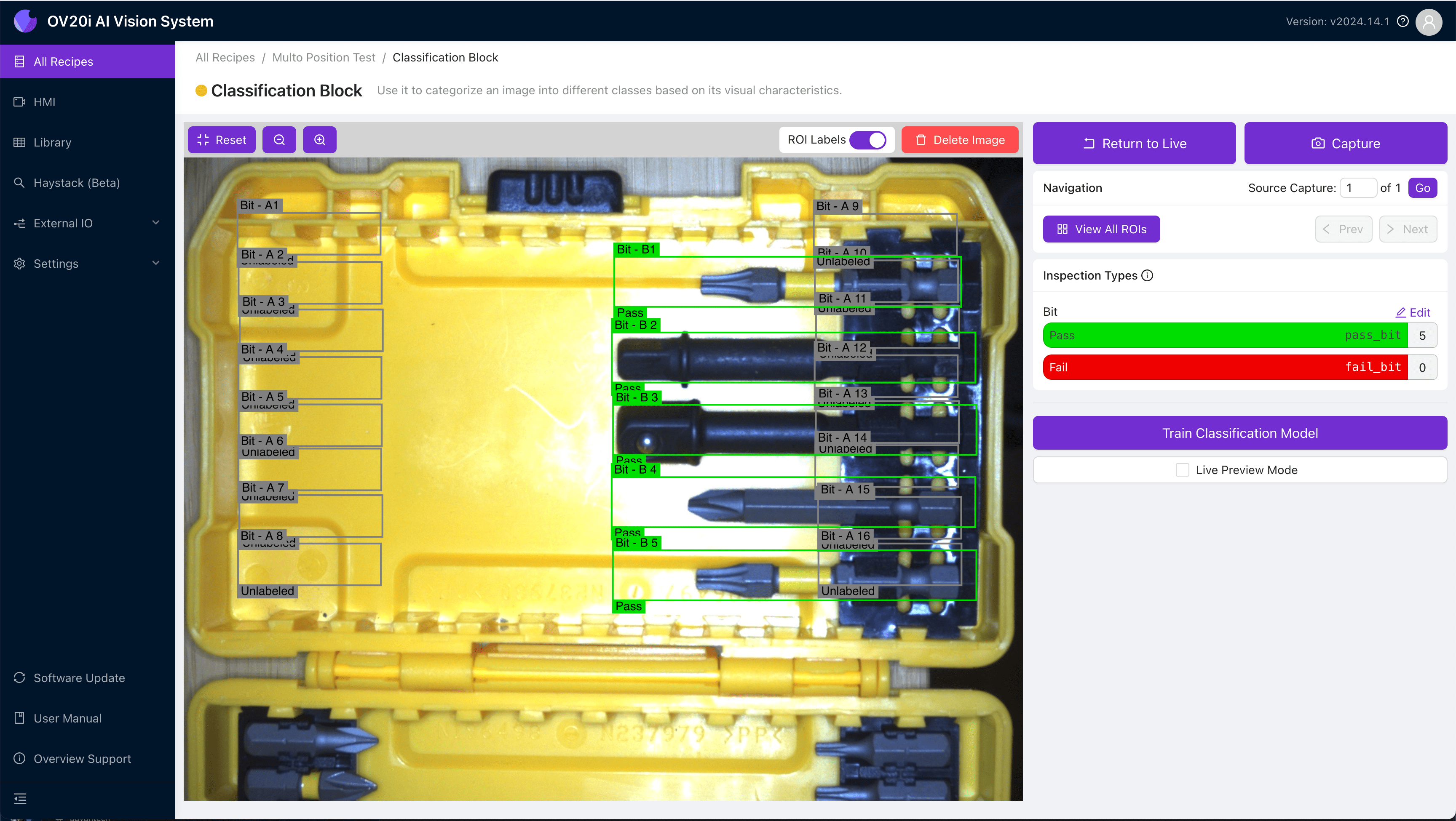
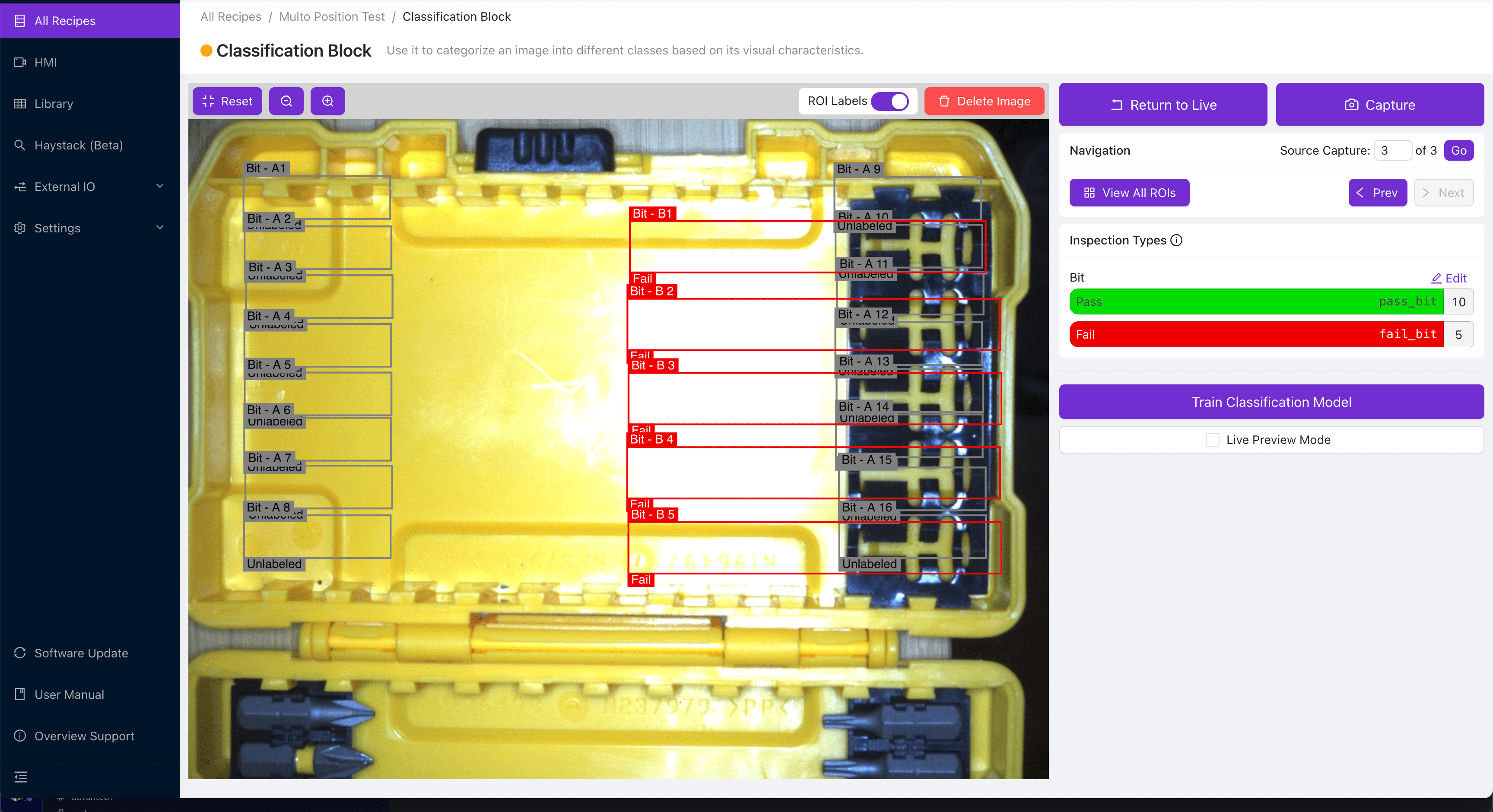
- Etiquete y entrene el modelo de clasificación usando imágenes de ambos lados A y B. Al capturar y etiquetar el lado A, no etiquete los ROIs del lado B y viceversa.
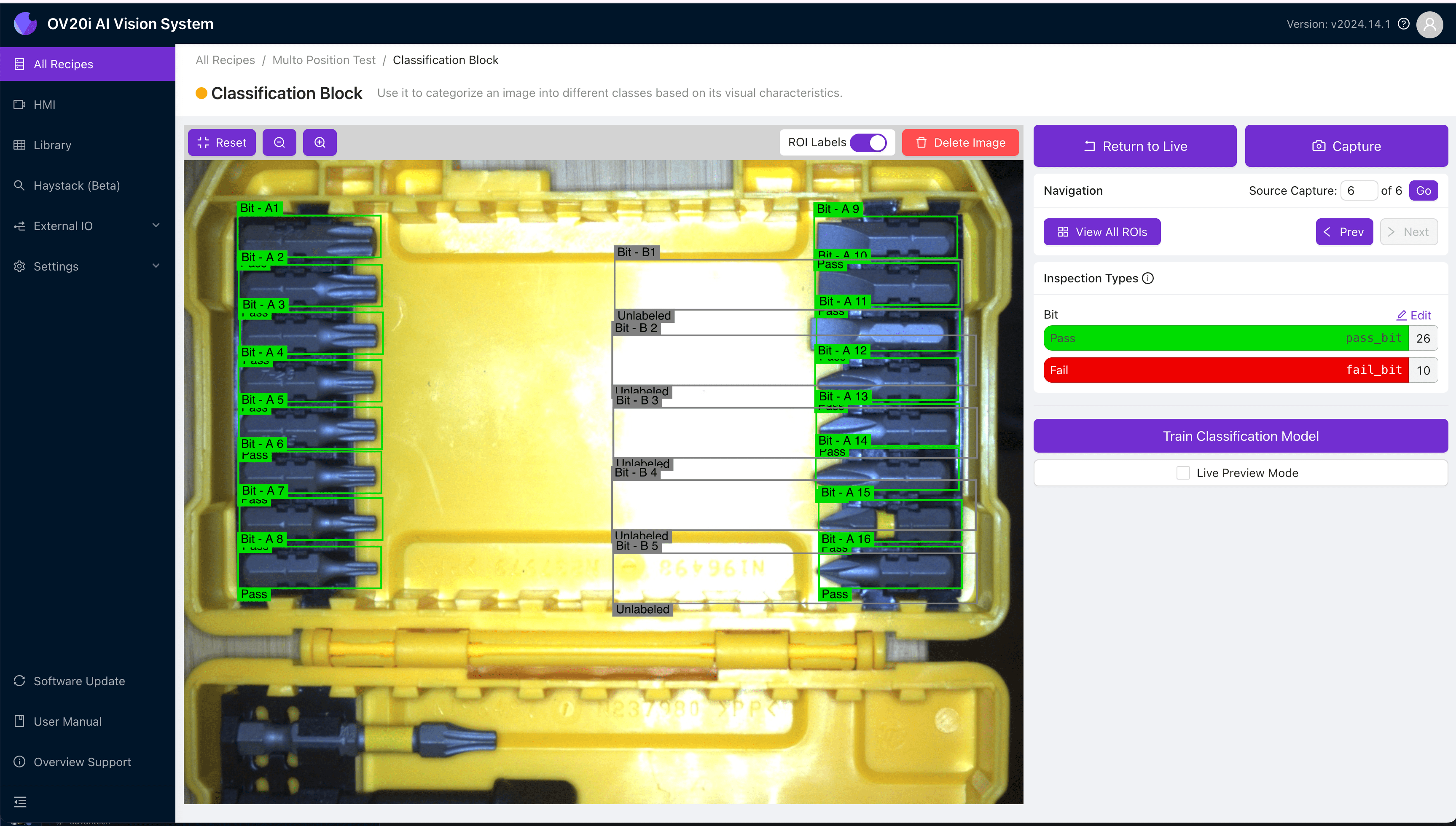 | 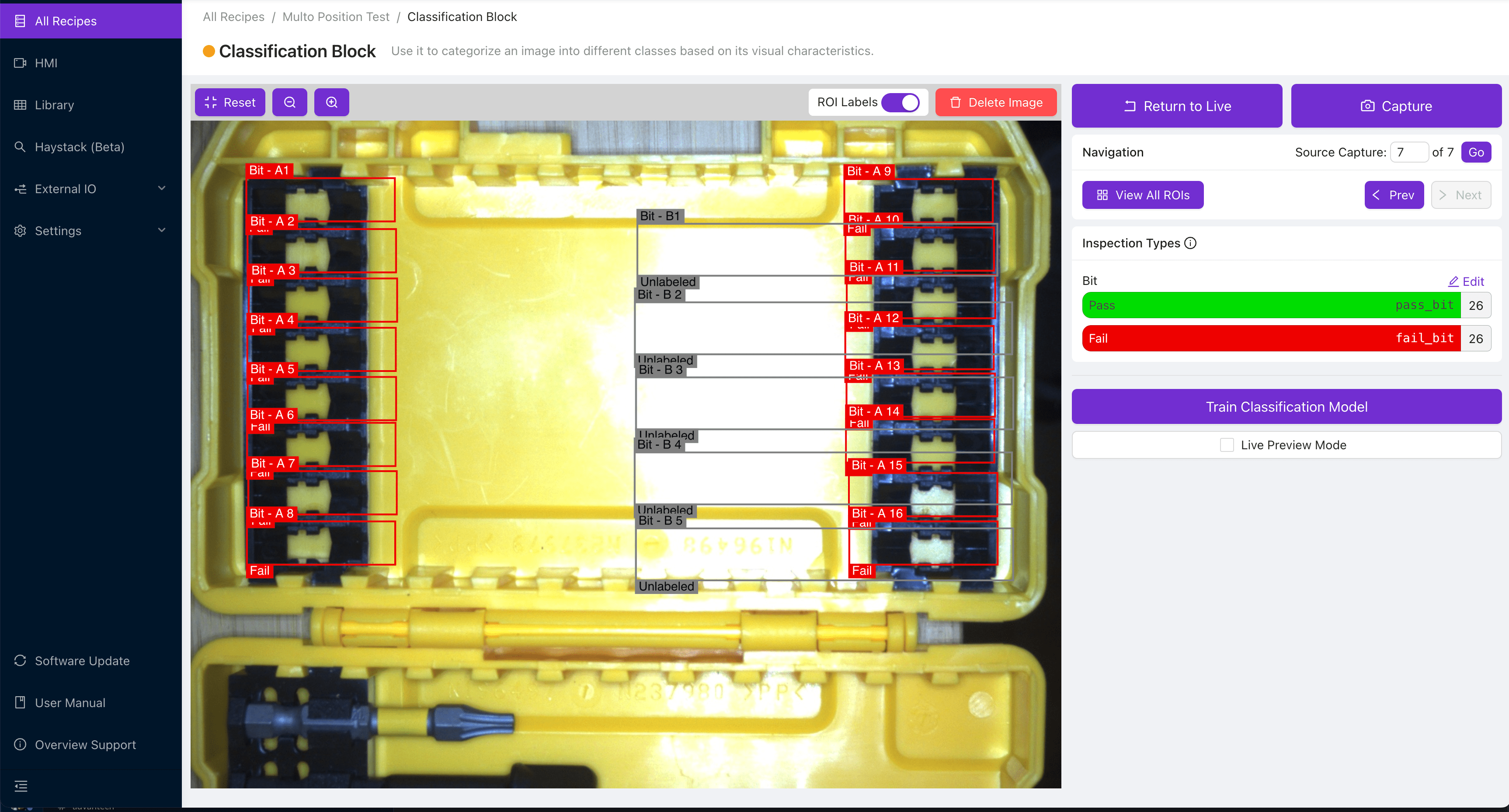 |
|---|---|
| Etiquetando lado A (Aprobar) | Etiquetando lado A (Fallar) |
 |  |
| Etiquetando lado B (Aprobar) | Etiquetando lado B (Fallar) |
Configurar la Lógica de Node-RED
-
Navegue al Bloque IO (Configure IO desde el editor de recetas) para abrir su flujo de Node-RED.
-
Cree una fuente para indicarle al OV10i cuál lado se está inspeccionando actualmente.
Estos pueden ser datos de posición del robot, información del PLC, o cualquier otra cosa que desee utilizar. En el siguiente ejemplo, simularemos esto usando dos nodos Inject, uno que envía la cadena "A" y otro que envía la cadena "B".
- Dado que los datos del lado entrantes pueden ser momentáneos, pero queremos verificar cuál lado está activo, almacenaremos los datos de estado usando una variable Flow, que persistirá hasta que se reciba la información del siguiente lado. Conecte su fuente de datos a un bloque function que contenga el siguiente código:
flow.set('side',msg.payload);
return msg;
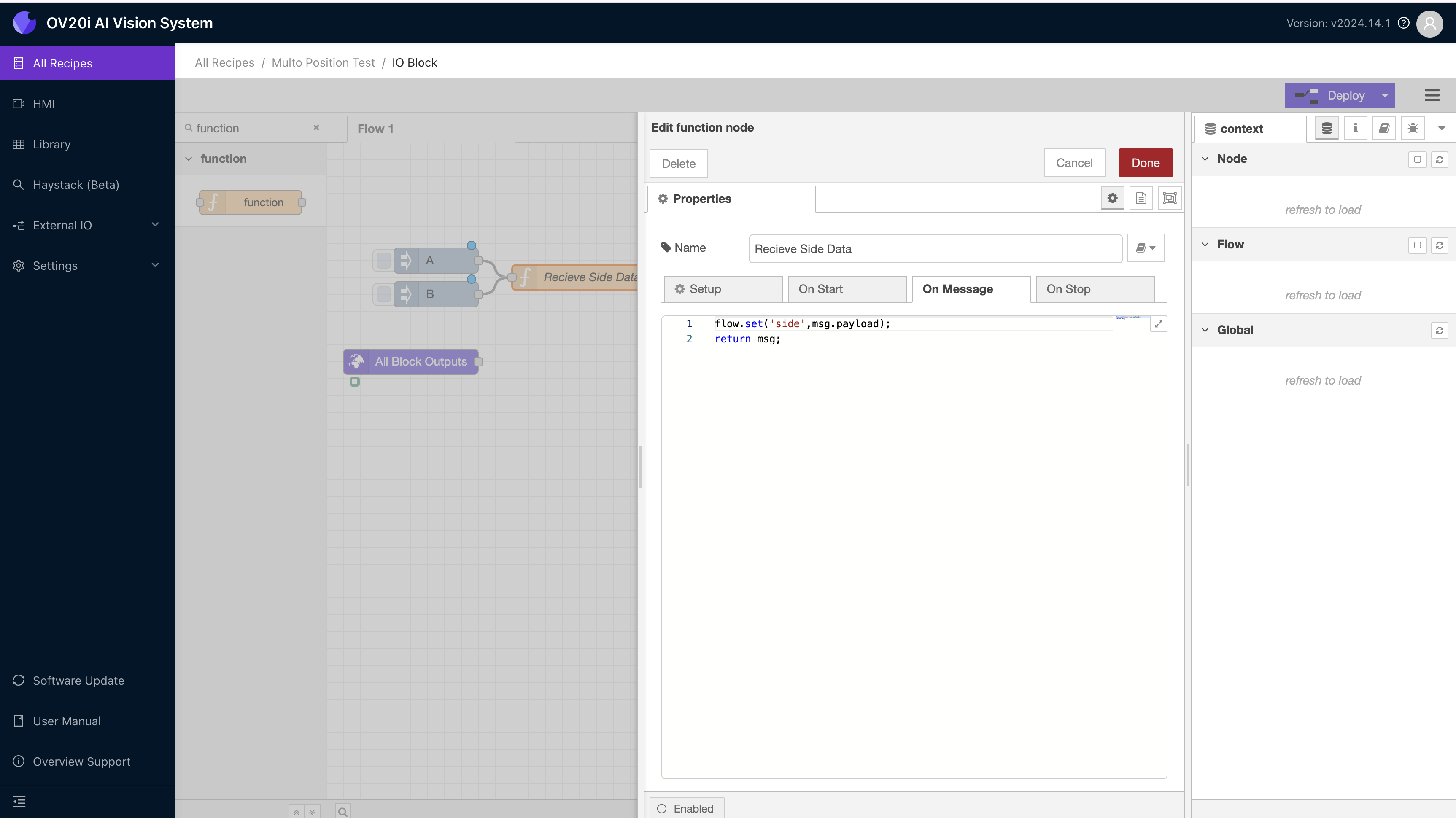
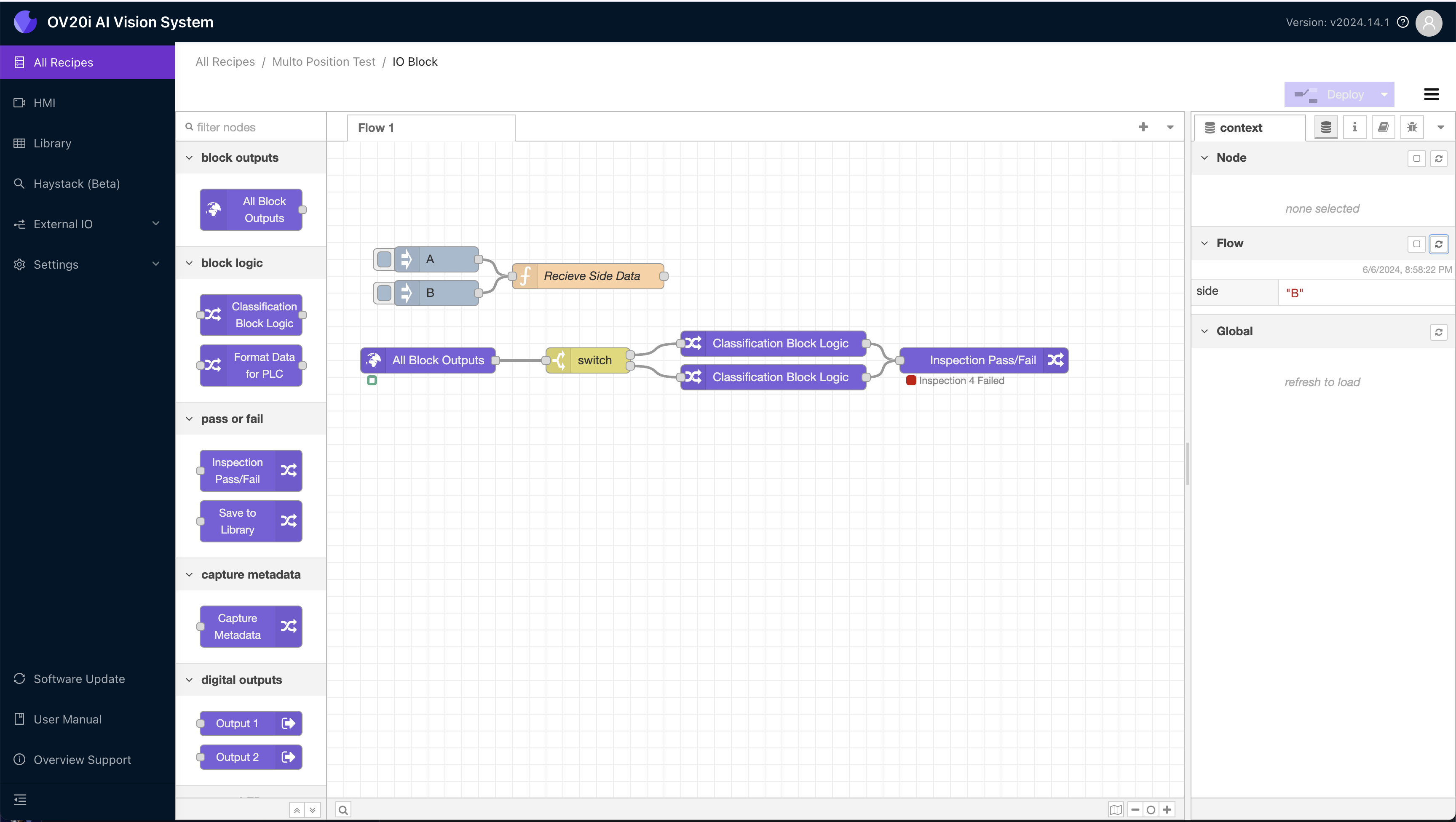
- Puede probar si los datos de su lado se están almacenando correctamente abriendo la barra lateral de datos de context, enviando un mensaje y luego presionando refresh en el panel de la variable Flow. El panel de datos del flujo solo se actualizará cuando se actualice manualmente usando el pequeño botón refresh.
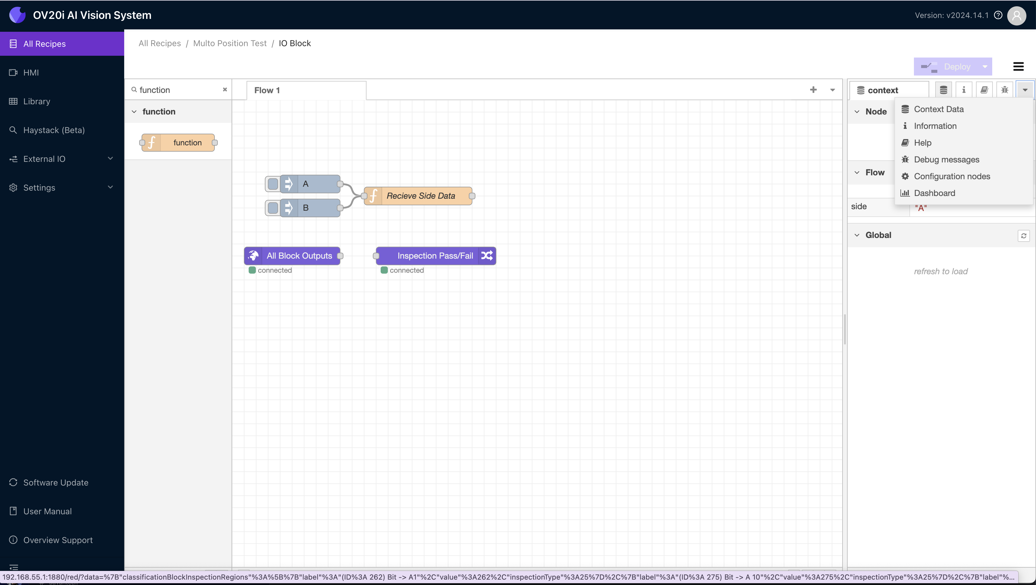
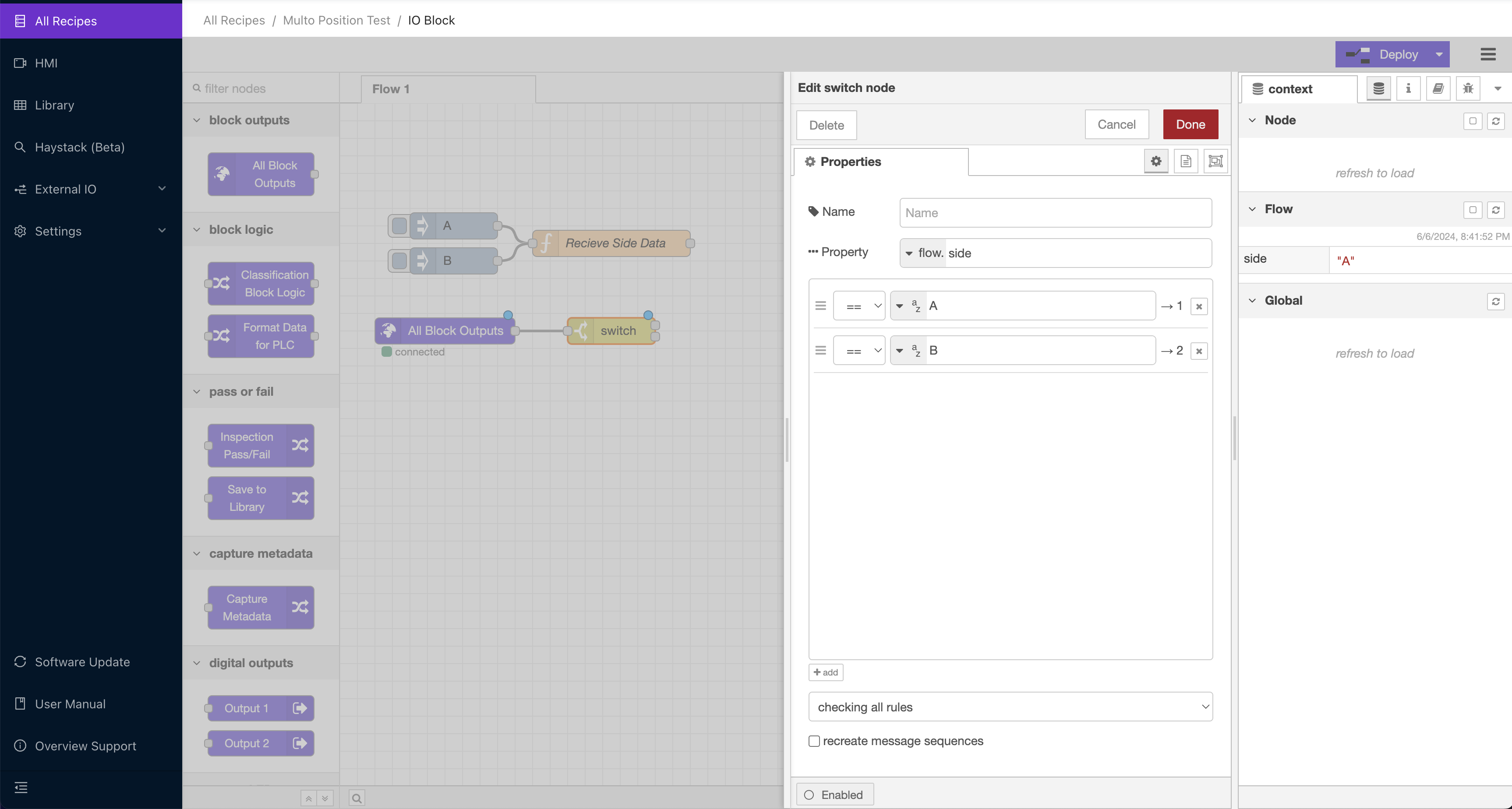
- Una vez que los datos del lado estén correctamente almacenados en la variable Flow, agregue un nodo switch conectado a All Block Outputs. Este será el bloque que enrute el mensaje con los datos de inspección según cuál lado esté activo en la variable Flow. Configúrelo para que mire la variable Flow y enrute el mensaje al puerto 1 si A está activo y al 2 si B está activo.
Para recetas más complejas, repita este proceso para tantas vistas diferentes como desee inspeccionar.
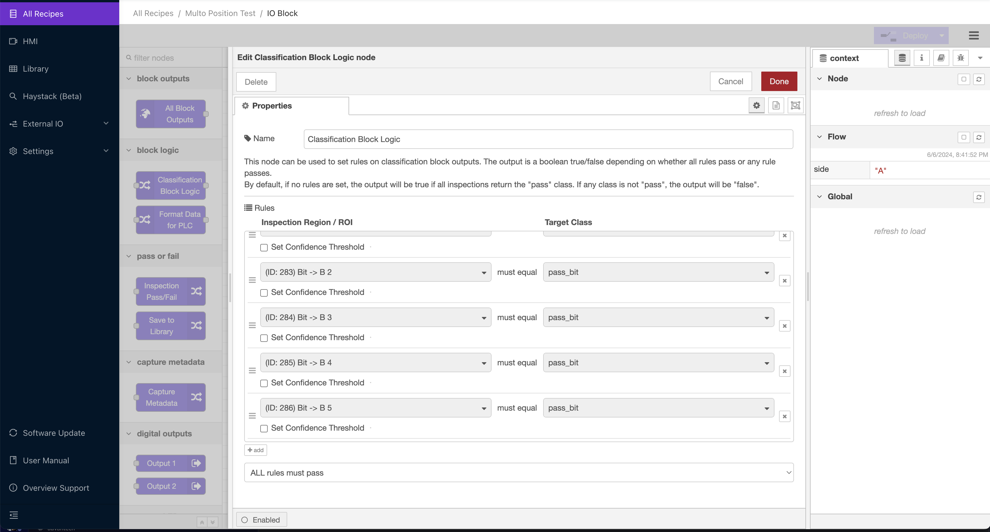
- Conecte cada puerto de salida del switch a un bloque Classification Block Logic, y configure cada uno según las reglas que desee inspeccionar para ese lado. El nodo switch solo enrutará un mensaje a uno de los nodos a la vez. La imagen a continuación muestra la configuración para el puerto del lado B del switch. Observe que no hace referencia a ninguno de los ROIs de A, por lo que la lógica ignorará los resultados de ese lado cuando la inspección se enrute a través de este nodo.
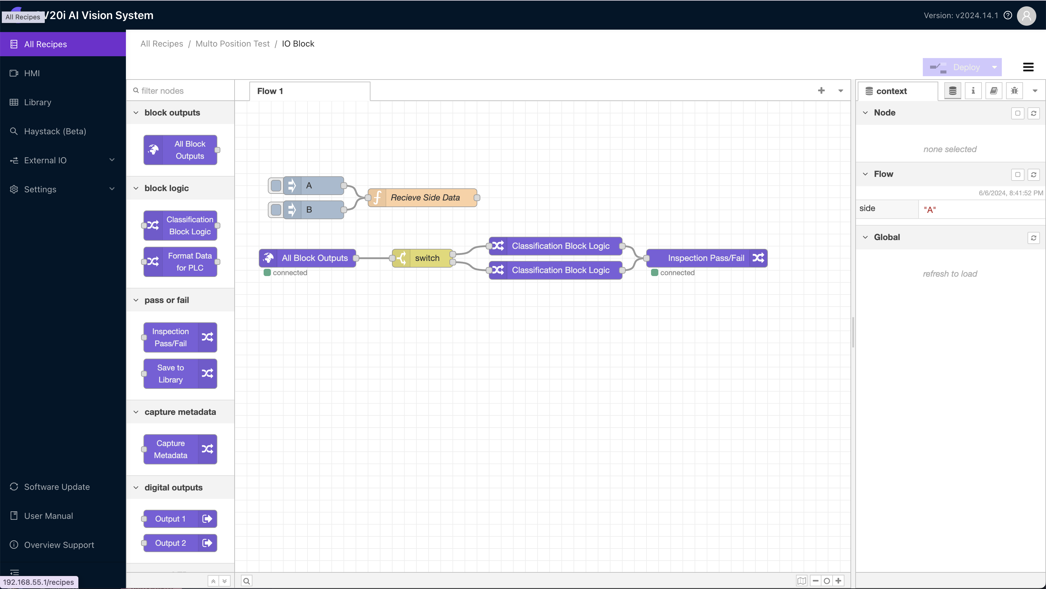
- Finalmente, conecte los bloques de lógica al bloque Inspection Pass/Fail. Esto permite que los resultados se muestren en la HMI, así como que se transmitan a cualquier PLC conectado u otro componente del flujo.
Probar la Receta
Ahora que el flujo de Node-RED está configurado, es momento de probar la receta de extremo a extremo.
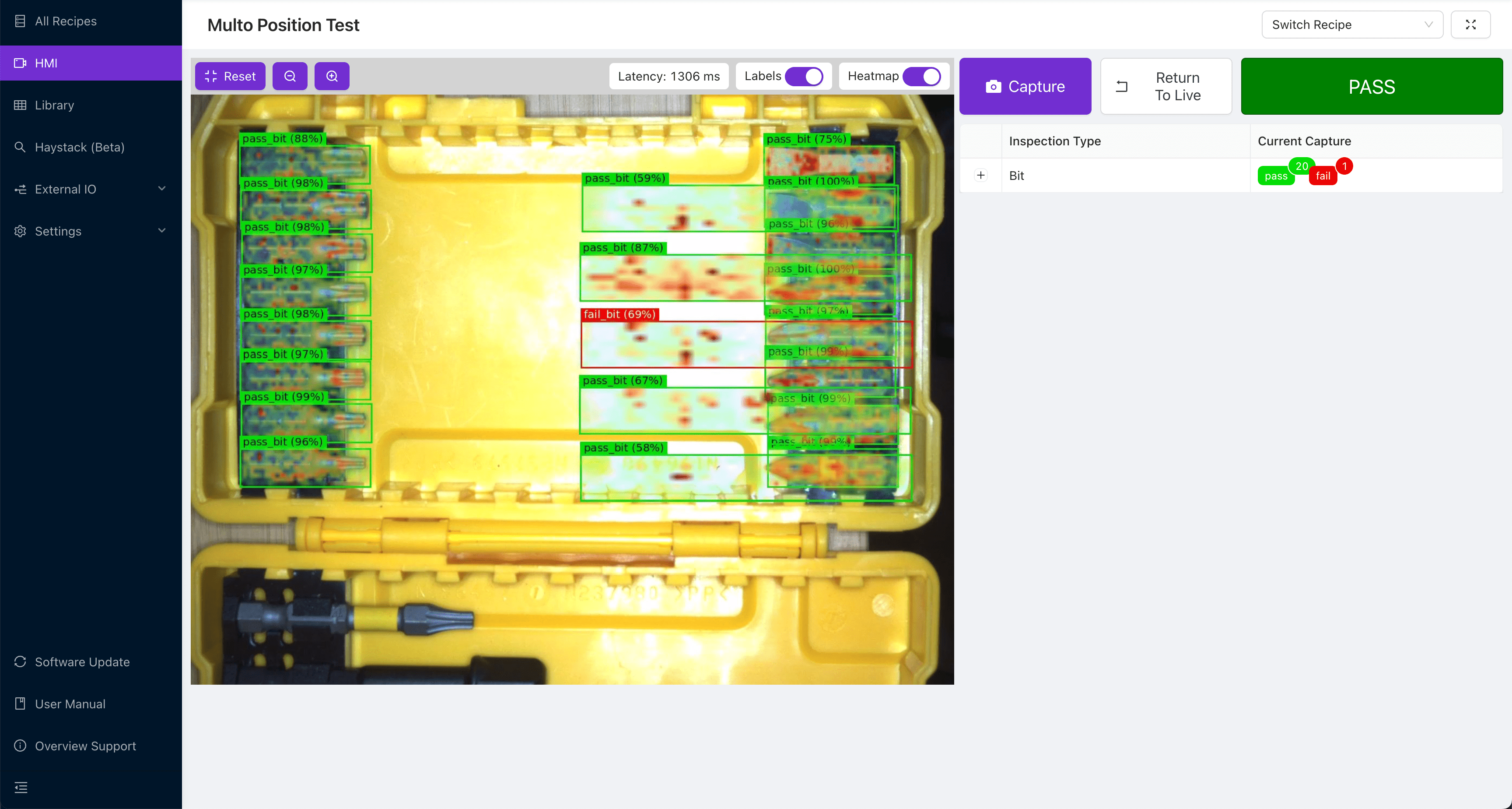
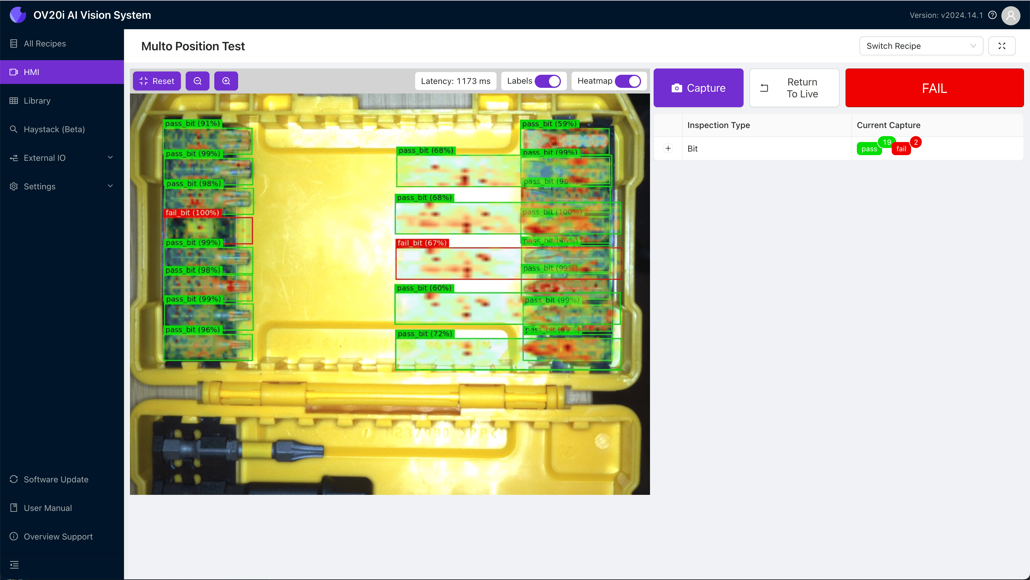
- Primero, enviaremos el comando del lado A usando nuestro nodo inject de Node-RED. Luego, usaremos la HMI para inspeccionar una pieza buena. Observe cómo, a pesar de que una de las regiones del lado B falló, toda la inspección fue aprobada.
- Ahora, cuando retiramos una broca del lado A e inspeccionamos nuevamente, obtenemos el resultado de falla que queremos.
- Pasando al lado B, enviamos la señal B usando nuestro inject de Node-RED y presionamos refresh en la sección de la variable Flow del panel de datos de contexto para asegurarnos de que esté almacenada.
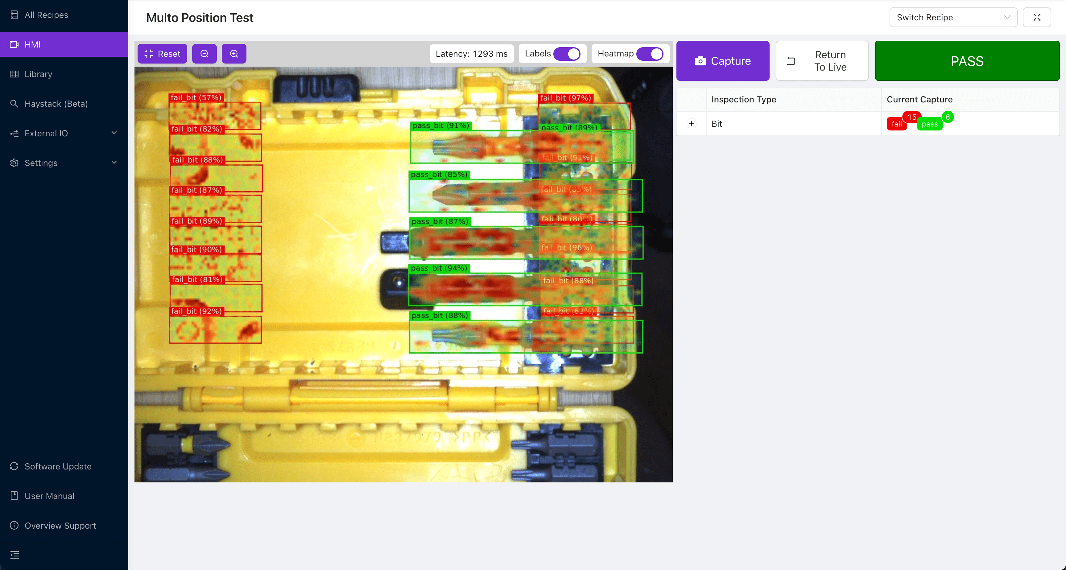
- Ahora, cuando volteamos al lado B de una pieza buena, vemos que la inspección pasa a pesar de que todas las regiones del lado A fallan.
¡Felicitaciones! Ahora sabe cómo usar una sola receta y modelo a través de múltiples vistas de una pieza. Esto permitirá inspecciones complejas a altas velocidades y una integración estrecha con los robots. También le ahorrará un tiempo significativo que se gastaría entrenando múltiples modelos que realizan la misma inspección, solo en diferentes vistas.