AI-POWERED DOCS
What do you want to know?
Industrial Ethernet (PLC Integration)
OV Spark talks to a PLC over EtherNet/IP or PROFINET. Both carry the same data; they are two ways of framing one process image.
Choose a protocol
Go to Integration → Industrial Ethernet:
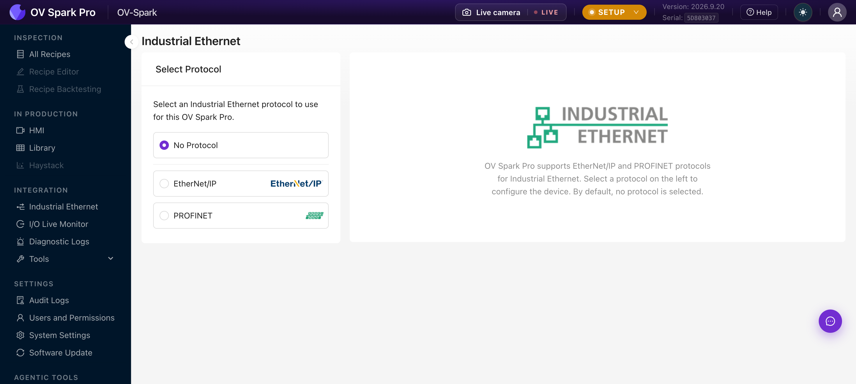
| Option | Use when |
|---|---|
| No Protocol | Default. Digital I/O only, no fieldbus |
| EtherNet/IP | Allen-Bradley / Rockwell and other CIP controllers |
| PROFINET | Siemens and other PROFINET controllers |
Selecting a protocol changes how the camera presents itself on the network, so do it while the line is stopped.
The process image
Whichever protocol you choose, the camera exchanges a single fixed process image with the controller:
| Direction | Size |
|---|---|
| Camera to PLC (input) | 500 bytes |
| PLC to camera (output) | 496 bytes |
On EtherNet/IP this is one assembly pair. On PROFINET the same bytes are carved into modules. The content is identical either way, so a recipe developed against one protocol behaves the same on the other.
The byte and bit layout is generated from a single source alongside the firmware, and it moves with the firmware version. Import the EDS (EtherNet/IP) or GSDML (PROFINET) file that matches your camera's firmware and let your PLC software lay out the tags. Transcribing offsets by hand is how installs end up reading the wrong word after an update.
Contact support@overview.ai for the EDS, GSDML, or sample ladder logic for your firmware version.
Set up EtherNet/IP
- In Integration → Industrial Ethernet, select EtherNet/IP and apply
- Import the EDS file for your firmware into your PLC software, for example Studio 5000 via Tools → EDS Hardware Installation Tool
- Add the camera as a module in the I/O configuration
- Set the connection parameters, including the requested packet interval
- Verify the connection in I/O Live Monitor
The device will not appear in the module catalog until the EDS is installed. Doing this first saves a confusing hunt through the catalog.
Set up PROFINET
- In Integration → Industrial Ethernet, select PROFINET and apply
- Install the GSDML file for your firmware into your engineering tool, for example TIA Portal
- Add the camera to the network and assign its device name
- Map the modules into your process image
- Verify the connection in I/O Live Monitor
Verify the link
Integration → I/O Live Monitor shows the handshake as it happens:
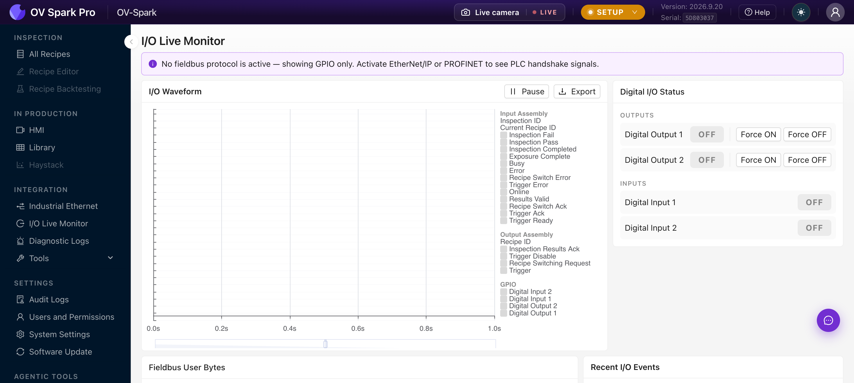
With a protocol active you can watch the Input Assembly and Output Assembly signals, including inspection ID, recipe ID, pass and fail bits, trigger acknowledgement, and the recipe switch handshake. Fieldbus User Bytes and Recent I/O Events sit below.
If no protocol is active, the page says so and shows GPIO only. That message is the quickest way to catch a protocol that silently failed to apply.
Digital I/O Status has Force ON and Force OFF for each output. Force an output and watch your stack light or reject gate. If forcing works but the recipe does not, the fault is in the recipe, not the wiring.
Digital I/O alongside the fieldbus
Digital I/O keeps working while a fieldbus is active. Many lines use the fieldbus for results and recipe selection, and hard-wire the trigger for determinism.
See Pinouts for the trigger input, digital inputs, digital output, and strobe output.
Troubleshooting
| Symptom | Check |
|---|---|
| Camera not in the module catalog | The EDS or GSDML was not installed, or does not match the firmware |
| Connects then drops | Requested packet interval too aggressive, or a duplex mismatch. See Link diagnostics on the Network page |
| Tags read the wrong values | Layout came from a different firmware version. Reimport the generated file |
| No handshake at all | Confirm a protocol is selected; I/O Live Monitor will say if it is showing GPIO only |