AI-POWERED DOCS
What do you want to know?
Pinouts (M12 Power & I/O)
OV Spark carries all power, digital I/O, and the reset signal on a single M12 12-pin connector on the bottom of the housing. Tick what you are connecting and you get every core to land.
What are you connecting?
Tick what is on your line. The table lists every core to land on the flying-leads cable.
| Pin | Camera core | Signal | Connect to |
|---|---|---|---|
| 7 | Black | Vin+ | +24 V supply |
| 8 | Gray | GND | 0 V supply |
| 10 | Violet | Trigger | Sensor signal output |
| 9 | Red | DIO GND | Sensor 0 V, and the supply 0 V |
| 11 | Orange | DO0 | Load negative. Load positive goes to +24 V |
Wiring a specific sensor model or PLC? The IO Helper builds a full diagram for OV Spark, with the other device's own wire colours.
- Same connector, pinout and cable colours as the OV80i
- Black is Vin+ and Gray is ground on this cable, the reverse of what most people expect
- Power on pins 7 and 8, trigger on pin 10, digital output on pin 11, strobe or second output on pin 12
- The same connector takes the Overview PoE adapter
Connector face
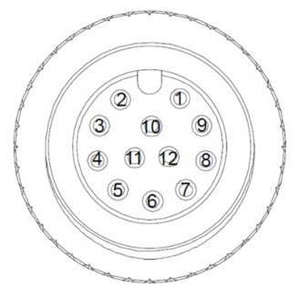
Pin assignment
| Pin | Signal | Function |
|---|---|---|
| 1 | Digital Input 1 | Opto-isolated input |
| 2 | Reserved | Not connected |
| 3 | Reserved | Not connected |
| 4 | Reset System | Pull to reset the camera |
| 5 | Digital Input 0 | Opto-isolated input |
| 6 | Digital Input Common | Supply rail for the input opto-isolators (10–30 V) |
| 7 | Vin+ | System power in, +24 V |
| 8 | Vin− | System power in, ground |
| 9 | Digital GND | Reference for digital I/O |
| 10 | Trigger Input | Hardware trigger, pull to Digital GND |
| 11 | Digital Output 0 | Sinking output |
| 12 | Digital Output 1 / Strobe Out | Shared output, selectable function |
OV Spark uses the same M12 A-coded 12-pin Power & I/O pinout as the OV80i, pin for pin. Wiring, breakout boxes and cable assemblies are interchangeable between the two.
The one difference is pin 12: on the OV80i it is Digital Output 1, while on OV Spark the same pin is a shared Digital Output 1 / Strobe Out with a selectable function.
The OV10i and OV20i use a 17-pin connector with a completely different layout. Do not carry wiring across from those.
Wire colour reference
The flying-leads Power & I/O cable uses the same colour code as the OV80i, since it is the same connector.
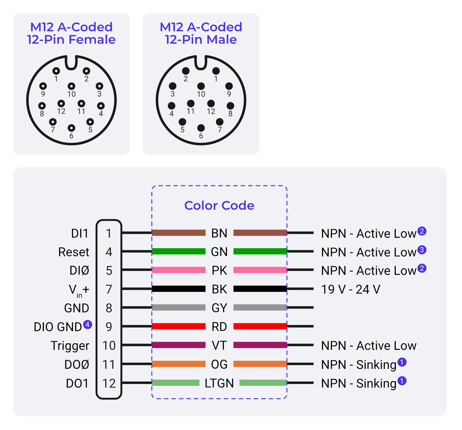
| Pin | Signal | Wire colour | Notes |
|---|---|---|---|
| 1 | DI1 | Brown (BN) | NPN, active low |
| 4 | Reset | Green (GN) | NPN, active low |
| 5 | DI0 | Pink (PK) | NPN, active low |
| 7 | Vin+ | Black (BK) | 19 V to 24 V |
| 8 | GND | Gray (GY) | Power ground |
| 9 | DIO GND | Red (RD) | Digital I/O ground |
| 10 | Trigger | Violet (VT) | NPN, active low |
| 11 | DO0 | Orange (OG) | NPN, sinking |
| 12 | DO1 | Light Green (LTGN) | NPN, sinking. Shared with Strobe Out on OV Spark |
Pins 2, 3 and 6 are not brought out on the flying-leads cable.
On this cable Black (BK) is Vin+ and Gray (GY) is power ground. That is the opposite of the convention most people carry in from general electrical work, and it is the single easiest way to destroy a camera on a bench.
Check the colour against this table before you apply power, every time.
The Overview PoE adapter CB-POE25-RJ45F-M12A12F-1 mates with this same 12-pin connector and feeds the camera from an 802.3af or 802.3at source. See Power over Ethernet.
Pin 8 (Vin−) is the power return. Pin 9 (Digital GND) is the reference for the trigger and the outputs. Keep them straight: sensors and loads reference pin 9, the power supply references pin 8.
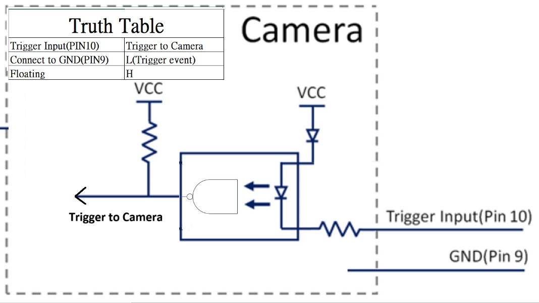
Some platform documentation lists pin 10 under "reserve". On OV Spark it is the hardware trigger input, with a pulse duration of 0–8192 µs. Wire your trigger sensor to pin 10 and Digital GND (pin 9).
Powering the camera
Connect pin 7 to +24 V and pin 8 to 0 V from a regulated 19–24 VDC supply. The camera draws 12 W typically and 17 W peak, so a supply rated for at least 24 W gives comfortable headroom.
Trigger input
Pulling pin 10 down to Digital GND (pin 9) generates a trigger event. Leaving it floating holds the line high, so no capture occurs.
| Parameter | Specification |
|---|---|
| Pulse duration | 0–8192 µs |
| Software interrupt | No |
Digital inputs
The two digital inputs (pins 5 and 1) are opto-isolated and share a common supply rail on pin 6. Connect pin 6 to your 10–30 V control voltage, then switch the input pin to ground to activate it.
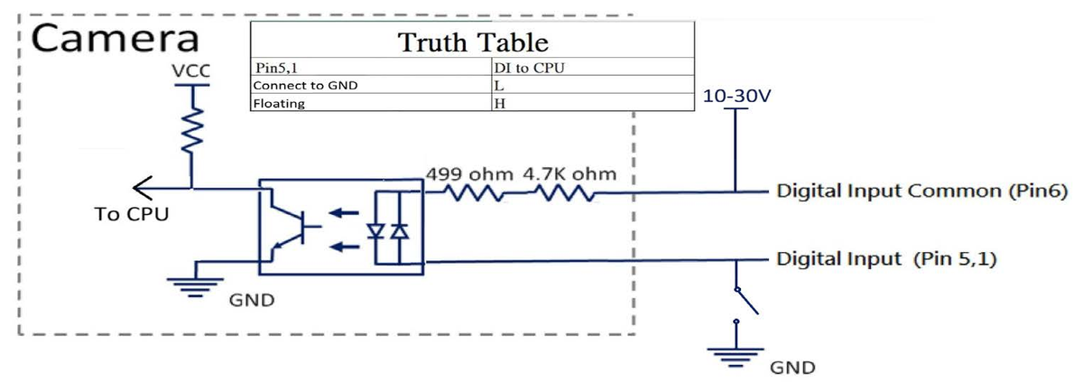
| Parameter | Specification |
|---|---|
| Input voltage | High: 10–30 VDC, Low: 0–3 VDC |
| Input current | Max 10 mA |
| Frequency | Max 60 Hz |
| Response time | Max 18.8 µs |
| Software interrupt | Yes |
Digital output
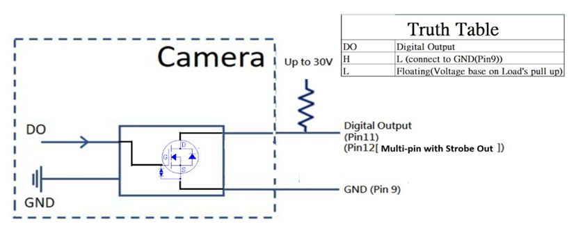
Pin 11 is a sinking output. When active it pulls the line to Digital GND; when inactive it floats, so the voltage sits wherever your load's pull-up puts it.
| Parameter | Specification |
|---|---|
| Sink voltage | Up to 30 V |
| Sink current | Typical 0.2 A |
| Frequency | Max 60 Hz |
| Response time | Max 8 µs |
Like every Overview camera, the digital outputs pull to ground when active and cannot supply +24 V. Wire the load between +24 V and the output pin. Anything above 30 V or 0.2 A needs a relay.
Strobe output
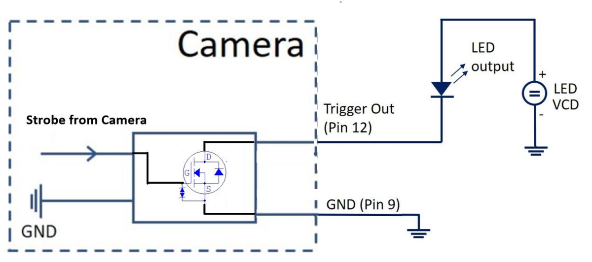
Pin 12 doubles as a second digital output and as a strobe output for an external light. Its faster response time suits strobe timing.
| Parameter | Specification |
|---|---|
| Sink voltage | Up to 30 V |
| Sink current | Typical 0.2 A |
| Frequency | Max 60 Hz |
| Response time | Max 4.5 µs |
OV Spark has 8 programmable white LEDs on board. Reach for the strobe output only when you need an external light the built-in ring cannot cover, such as backlighting or a very large field of view.