AI-POWERED DOCS
What do you want to know?
Step 5: Outputs
Judgment decided the verdict. Outputs decides who hears about it: a PLC over the fieldbus, a wire on the camera, or both. If a PLC reads more than one recipe, plan the slots across all of them first:
PLC slot planner
Lay your recipes side by side and give each full slot one meaning everywhere.
| Slot | On the wire | |||
|---|---|---|---|---|
| 1 | 96 to 119 | Meaning changes | ||
| 2 | 120 to 143 | Meaning changes | ||
| 3 | 144 to 167 | |||
| 4 | 168 to 191 | |||
| 5 | 192 to 215 | |||
| 6 | 216 to 239 | |||
| 7 | 240 to 263 | |||
| 8 | 264 to 287 |
| Byte | Field | Meaning |
|---|---|---|
| 96 | Type | 6, Barcode Read |
| 97 | Status | Pass, judgment, N/A, enabled and ran bits |
| 98 | Error | 0 means none |
| 100 | Score x1000 | 1000 decoded, 0 not decoded |
| 104 | F1 Symbology | |
| 108 | F2 MatchOutcome | |
| 112 | F3 FailureCause | |
| 116 | F4 | Not used by this tool type |
Pass bit for slot 1: byte 28, bit 0. The decoded barcode text is not in this record; it is sent in the user results area. Slots 9 to 64 carry a pass bit only, with no record.
A planning aid. The camera's own Bytes view on the Outputs step, and the EDS or GSDML for your firmware, are the authority on the layout.
- PLC recipe ID: the number a PLC selects this recipe by. Duplicate and import give a recipe a new one
- Slots: 1 to 8 send a full result, 9 to 64 a pass bit. Keep each slot meaning the same across recipes
- Output lines: two wires, DO0 and Strobe Out. The default new line is already a reject gate
- Outputs never block activation. A recipe with none is valid
The step has three sections, and they are independent. A recipe can use one, two or all three.
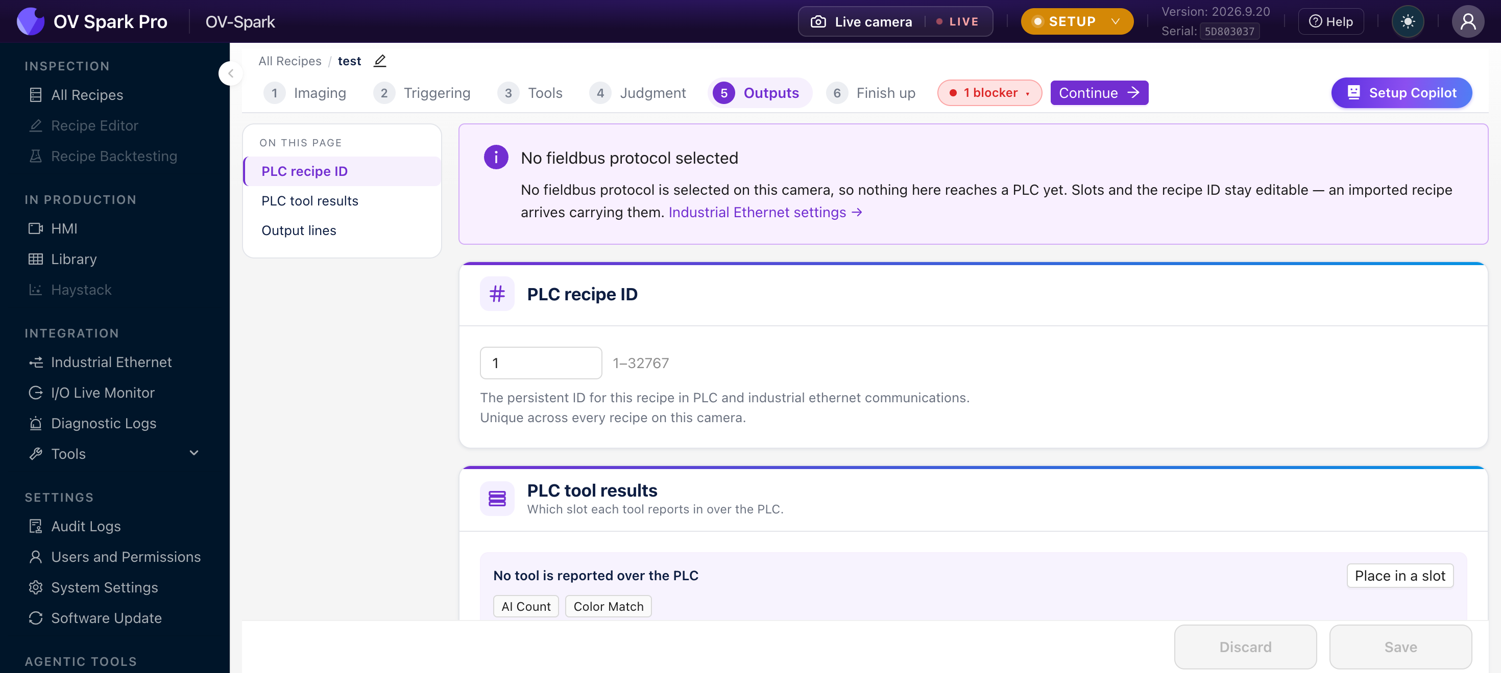
If no protocol is selected on the camera you get an info banner saying nothing here reaches a PLC yet, but slots and the recipe ID stay editable. That is deliberate: an imported recipe arrives carrying them, and you can configure now and commission later.
Pick a protocol in Industrial Ethernet when you are ready.
PLC recipe ID
A number from 1 to 32767 that identifies this recipe to a controller.
The persistent ID for this recipe in PLC and industrial ethernet communications. Unique across every recipe on this camera.
This is how a PLC selects a recipe remotely: it writes the ID and raises a switch request, the camera loads that recipe and acknowledges. It is also what appears in the recipe table on All Recipes.
The camera assigns an ID automatically when a recipe is created, so this field is never empty. IDs are unique across the whole camera, and trying to reuse one is refused with a message naming the recipe that already holds it.
This catches people out at commissioning. Duplicate and Import both assign a fresh ID, so the copy will not answer to the number your PLC program expects. Slot assignments do travel with an import, but the recipe ID does not.
After duplicating or importing, come back to this field and set the ID your controller actually selects.
The PLC writes the ID, raises the switch request, and the camera acknowledges, goes briefly offline while loading, then reports load complete. Inspections already running finish under the old recipe. An unknown ID raises a switch error rather than doing nothing silently.
The ID is the contract between the camera and the PLC program. Decide the numbering before you build the second recipe, keep it in the same document as your PLC tag list, and never reuse an ID for a different product.
A sensible scheme is one number per part number, so recipe ID 1204 inspects part 1204. Guessing later, from a camera in a cabinet, is miserable.
PLC tool results
This decides which slot each tool reports in over the PLC. A slot is a fixed position in the process image, so the controller always reads a given tool's result from the same address.
By default nothing is assigned, and the camera says No tool is reported over the PLC. The verdict still goes out; what is missing is the per-tool detail.
Two kinds of slot
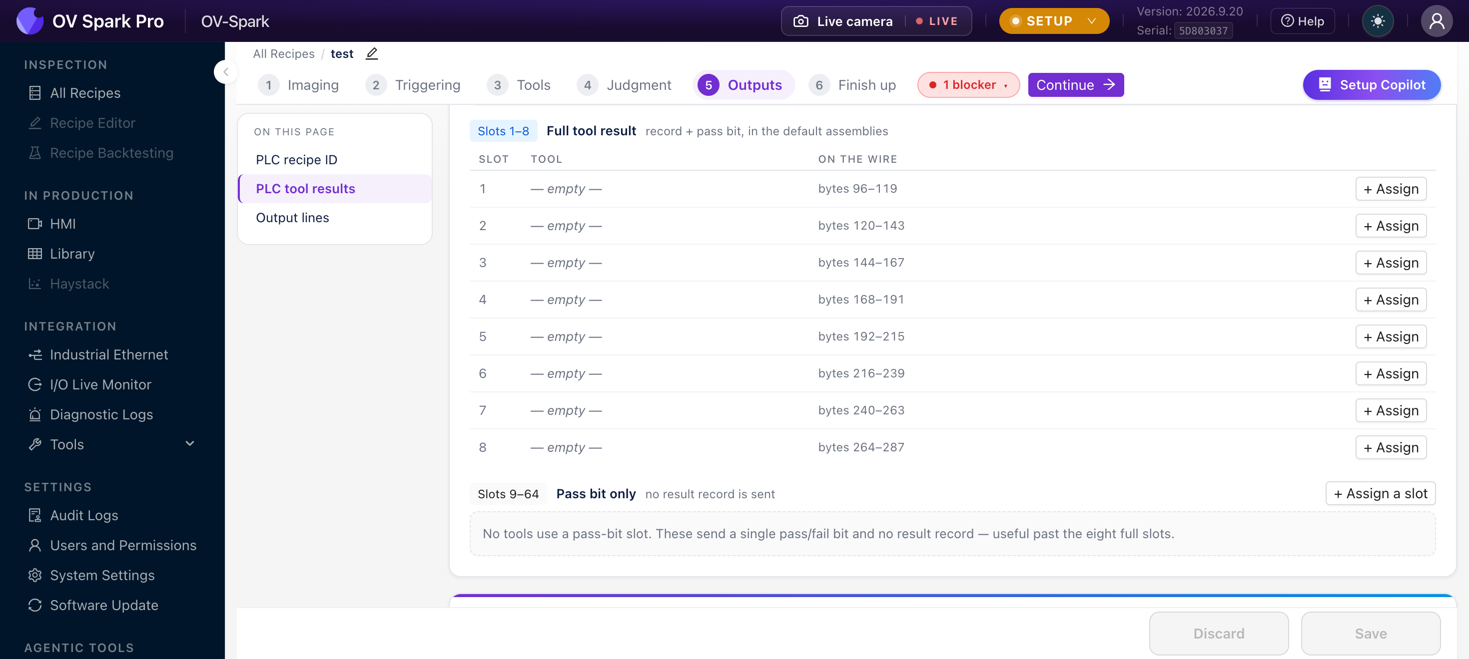
Slots 1 to 8: full tool result. A complete result record plus a pass bit, carried in the default assemblies. The table shows exactly where each lands:
| Slot | On the wire |
|---|---|
| 1 | bytes 96 to 119 |
| 2 | bytes 120 to 143 |
| 3 | bytes 144 to 167 |
| 4 | bytes 168 to 191 |
| 5 | bytes 192 to 215 |
| 6 | bytes 216 to 239 |
| 7 | bytes 240 to 263 |
| 8 | bytes 264 to 287 |
Each full slot is 24 bytes. Use + Assign on the row to put a tool there.
Slots 9 to 64: pass bit only. A single pass or fail bit, with no result record. As the camera puts it, these are useful past the eight full slots.
Choosing which tools get a full slot
You have eight full slots and up to 64 tools' worth of pass bits. The full slots are the scarce resource, so spend them where the controller needs a number, not just a verdict.
| Give a full slot to | Because the PLC wants |
|---|---|
| AI Count | The count itself, to log or compare |
| Color Match | The score or ΔE, to trend drift |
| AI OCR | The decoded text, for traceability |
| Barcode Read | The decoded code, to match against an order |
| AI Segmentation | Defect area, to grade rather than reject |
A pass bit is enough for a tool whose answer is genuinely binary, such as a classifier that only ever says good or bad.
Each record is 24 bytes: a small header carrying the tool type, status and error, a universal score, then four tool-specific values. Click Bytes on any assigned row and the camera shows you the exact field map for that slot, so nobody has to transcribe offsets by hand.
A Barcode Read record carries the symbology, whether the content matched, and a failure cause. The decoded string itself is sent separately, in the user results area of the input assembly. If your PLC needs the actual code, read it from there rather than from the tool record.
The first byte of every record says which tool type produced it. A controller that checks it cannot misread an OCR record as an alignment record after a recipe switch, which is the failure mode that keeping slot meanings stable is protecting you from.
Nothing stops recipe A putting a barcode in slot 1 and recipe B putting a count there. The camera will happily do it, and your PLC program then has to know which recipe is active before it can interpret the bytes.
That is a whole class of integration bug you can avoid by deciding once that slot 1 is always the barcode, slot 2 always the count, and leaving a slot empty in recipes that do not use it. Empty slots cost nothing.
A tool with no slot is not disabled. It runs, it judges, it appears in the Library, and it still gates the verdict if a judgment rule covers it. It simply is not reported individually to the PLC. The recipe's overall pass or fail still reaches the controller either way.
New tools always start unplaced, so this is the default state rather than a mistake.
Moving a tool between slots
Assigning is also how you reorder, and the behaviour differs depending on where the tool came from:
| You drop | onto an occupied slot | Result |
|---|---|---|
| A tool that already has a slot | The two tools swap slots | |
| A tool that is unplaced | The occupant is evicted off the PLC entirely |
Moving an unplaced tool into a slot that is already taken pushes the previous occupant out of the PLC map without warning. If a controller was reading that slot, it stops receiving that tool's record.
Check the unplaced strip after any slot reshuffle. Anything that fell off the map is listed there.
The Place in a slot button targets the lowest free full slot. Once all eight are taken it still opens, but every tool in the list is greyed out and nothing can be clicked, which reads like a bug.
To place a ninth tool, use + Assign a slot on the Slots 9 to 64 header instead and type a slot number.
Output lines
The third section switches a physical wire on the camera from the result.
Switch a wire on the camera from the result. Saved with this recipe.
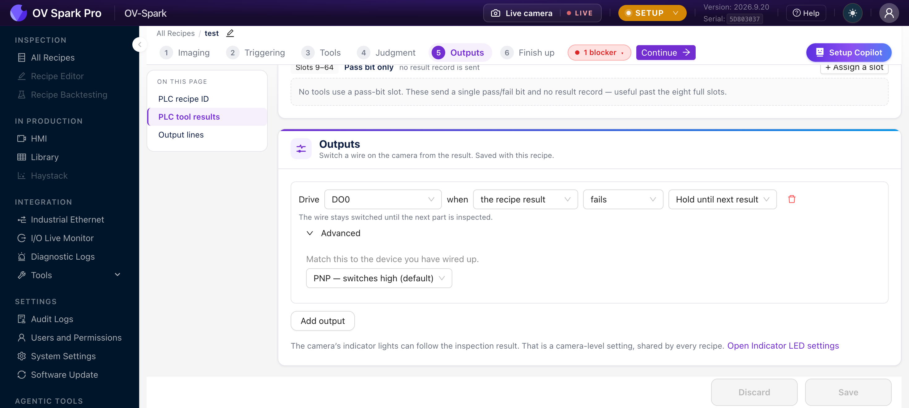
You get two output lines, one per physical pin. Once both are in use the Add output button stays visible but disabled, with a tooltip explaining that both pins are already taken.
Each line reads as a sentence:
Drive
[DO0]when[the recipe result][fails][Hold until next result]
A newly added line arrives already configured as DO0, the recipe result, fails, hold until next result, PNP, which is the reject-gate wiring most lines want first. For a simple reject gate you can add the output and save without changing anything.
The four choices
Which wire
| Option | Notes |
|---|---|
| DO0 | Digital Output 0, pin 11 |
| Strobe Out | Pin 12, also usable for external lighting |
What drives it
| Option | Use when |
|---|---|
| the recipe result | The overall verdict. The normal choice for a reject gate |
| one tool | A single tool's result, so you can act on one specific failure |
Choosing one tool reveals a tool picker. Aligners are not offered, and a disabled tool appears tagged as disabled but will block saving, because a line driven by a tool that never runs would never fire.
Which way round
| Option | Typical use |
|---|---|
| passes | Drive a good-part indicator, or a gate that opens to let good parts through |
| fails | Drive a reject actuator or a fault lamp |
How long it stays switched
| Option | Behaviour |
|---|---|
| Hold until next result | The wire stays switched until the next part is inspected |
| Pulse | The wire switches for a set time each time it happens, from 10 to 60000 ms, opening at 100 ms |
Hold suits anything that needs the state to persist while the part travels to the actuator, which is most reject mechanisms.
Pulse suits anything edge-triggered, such as a counter input or a PLC that latches on a rising edge. If you pulse into something that samples slowly, make the pulse longer than the PLC scan time or it will be missed entirely.
Advanced: match the polarity to your wiring
Under Advanced on each line:
Match this to the device you have wired up.
| Option | Behaviour |
|---|---|
| PNP, switches high (default) | The output sources current |
| NPN, switches low | The output sinks current |
A polarity mismatch does not produce an error. The camera happily switches, and the device never responds, which sends people looking for a broken recipe or a failed camera.
Confirm against the device datasheet before you go hunting. The I/O Live Monitor will show the camera switching the line even when the device is not reacting, which is the fastest way to tell these apart.
Use Add output for a second line, for example pass on one wire and fail on another.
Indicator LEDs
At the bottom of the step:
The camera's indicator lights can follow the inspection result. That is a camera-level setting, shared by every recipe.
Open Indicator LED settings takes you there.
Unlike everything else on this page, the indicator LEDs are not saved with the recipe. Changing them changes every recipe on the camera. Worth knowing before you change it to suit one product.
How outputs behave on a running line
The sentence tells you what happens on a normal part. These are the cases that decide whether an integration is solid.
Hold follows the level, both ways. A line set to hold on fail raises when a part fails and drops again by itself on the next passing part. You do not need a second line to clear it.
Pulses queue rather than drop. If a second part triggers while a pulse is still high, that pulse is remembered and fired afterwards rather than being lost. A third arriving in the same window replaces the second.
If a line is driven by one tool, and that tool was skipped because alignment failed, the line receives no event at all and holds whatever state it was already in.
It does not drop, and it does not fire. A held reject line stays asserted; a cleared one stays clear. Pair this with the alignment miss policy on Judgment, or drive safety-relevant wires from the recipe result instead, which always produces an event.
Recipe switches clear the pins first. Every configured output is driven to its idle state when a recipe loads, so a line asserted by the outgoing recipe cannot stay stuck on.
Outputs fire in Setup. You do not need Production to test wiring. Trigger manually and watch the pin in the I/O Live Monitor.
A 10 ms pulse into a controller scanning every 20 ms may never be seen. If the receiving logic is not edge-latched in hardware, size the pulse above the scan time, or use hold instead.
Things that change your outputs from another page
Three edits elsewhere in the editor quietly rewrite what you set here.
| What you do | What happens to outputs |
|---|---|
| Delete a tool on Step 3 | Any output line driven by that tool is deleted, and its slot is freed |
| Disable a tool on Step 3 | A line driven by it becomes a save-blocking error, because it could never fire |
| Duplicate the recipe | Per-tool output lines are dropped; recipe-verdict lines are kept |
Slot changes and the rest of the step are saved through different calls. If a slot change fails part way, earlier slot changes have already landed while the recipe ID and output lines have not, and the unsaved marker stays up.
If a save errors, re-read the page rather than assuming nothing happened.
Worked examples
A reject gate and nothing else. Drive DO0 when the recipe result fails, hold until next result, PNP. No fieldbus, no slots. Wire pin 11 to the reject valve, see Pinouts. This is a complete, legitimate configuration.
Reporting to a PLC. Set the PLC recipe ID, place the barcode in slot 1 and the count in slot 2, and leave the classifier on a pass bit. Pick EtherNet/IP or PROFINET in Industrial Ethernet and download the EDS or GSDML from there so the controller gets the layout without anyone transcribing byte offsets.
Recipe selection from the line. Give each product's recipe a distinct PLC recipe ID matching the part number. The PLC writes the ID at changeover and the camera switches, so the operator changes nothing.
Before you move on
- PLC recipe ID set, and recorded alongside your PLC tag list
- Any tool the controller needs a number from has a full slot
- Slot meanings consistent with your other recipes
- Output line polarity matches the device actually wired up
- Hold or pulse chosen to suit what reads the signal, and the pulse is longer than the PLC scan
- Safety-relevant wires driven from the recipe result, not from a single tool that alignment can skip
- PLC recipe ID re-checked if this recipe was duplicated or imported