AI-POWERED DOCS
What do you want to know?
Install the Camera
Mount OV Spark, wire power and I/O, and confirm that it is ready before operating the software.
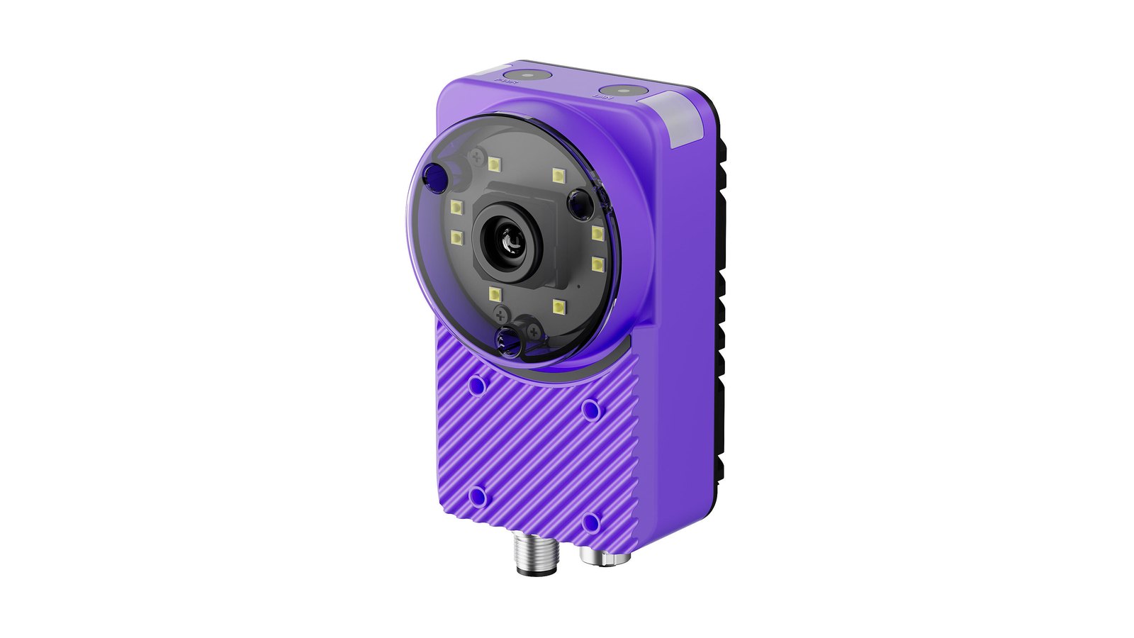
1. Mount the camera
OV Spark has four M3 tapped holes on the rear face on a 50 x 50 mm pattern, and four more on the front face on a 36 x 30 mm pattern, so you can mount it on a bracket from either side.
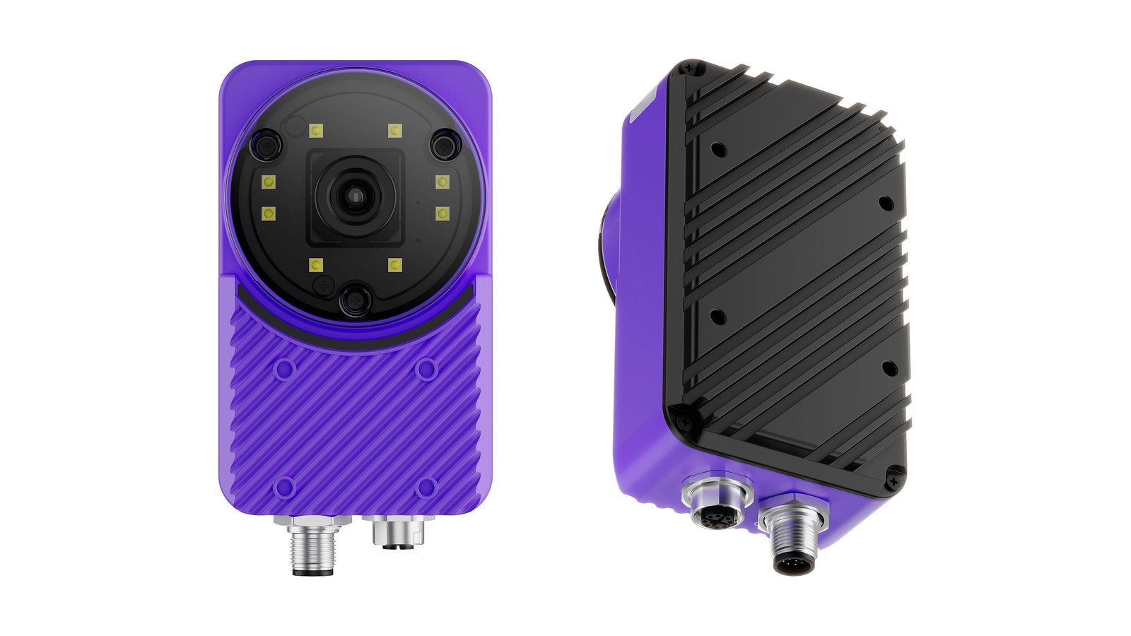
On the front, the four holes sit in the ribbed panel below the lens. On the rear, they are in the black heat sink.
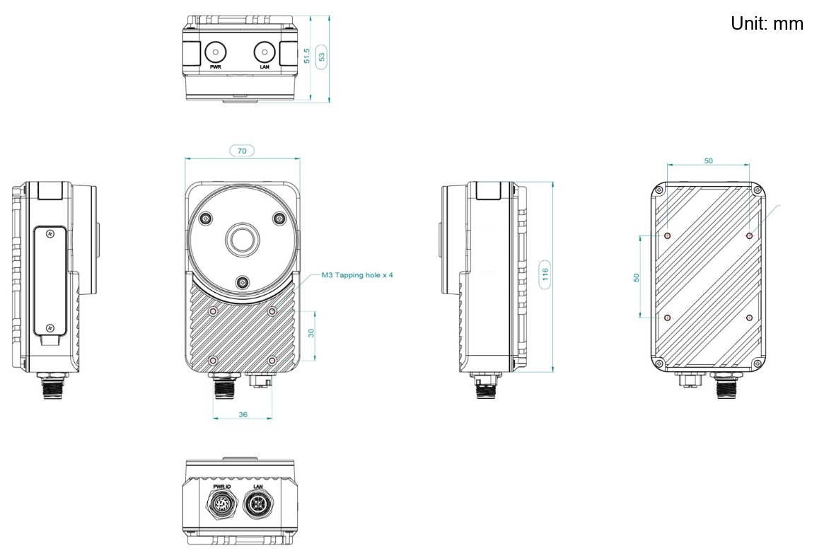
The body is 70 mm wide, 116 mm tall, and 53 mm deep. Both M12 connectors exit the bottom.
Both connectors exit the bottom face and increase the height of the camera to about 134 mm (from 116 mm) before any cable is attached. Leave clear space under the camera for the cable plugs and the bend radius of both cables, so nothing presses against a guard, a conveyor or the bracket.
When you choose a mounting height, work back from the field of view you need. With the standard 6 mm lens:
| Working distance | Field of view (H x V), 6 mm lens |
|---|---|
| 200 mm | 211.8 x 154.1 mm |
| 1000 mm | 1030.6 x 745.7 mm |
Try your own distance and part size in the field of view calculator. For mounting distance and minimum defect size, use Overview's optics calculators and choose your camera under Camera Model.
The camera aligns inspection regions against a template image. Any flex in the bracket shows up as drift in your results. Use a rigid mount and check it after the line has been running, not just when it is cold and still.
2. Identify the connectors
The bottom face carries the two M12 connectors; the side panel carries USB and the service buttons.
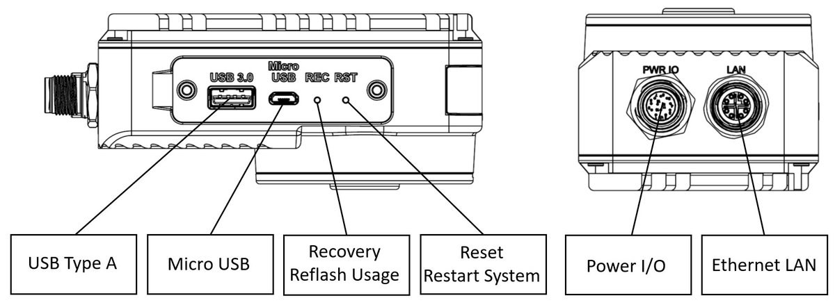
| Connector | Purpose |
|---|---|
| PWR I/O | M12 12-pin: power, digital I/O, trigger, reset |
| LAN | M12: Gigabit Ethernet |
| USB Type A | USB 3.0 peripheral, e.g. a Wi-Fi adapter |
| Micro USB | Recovery mode only |
| RSC | Recovery button, for reflashing |
| RST | Reset button, restarts the system |
3. Wire power and I/O
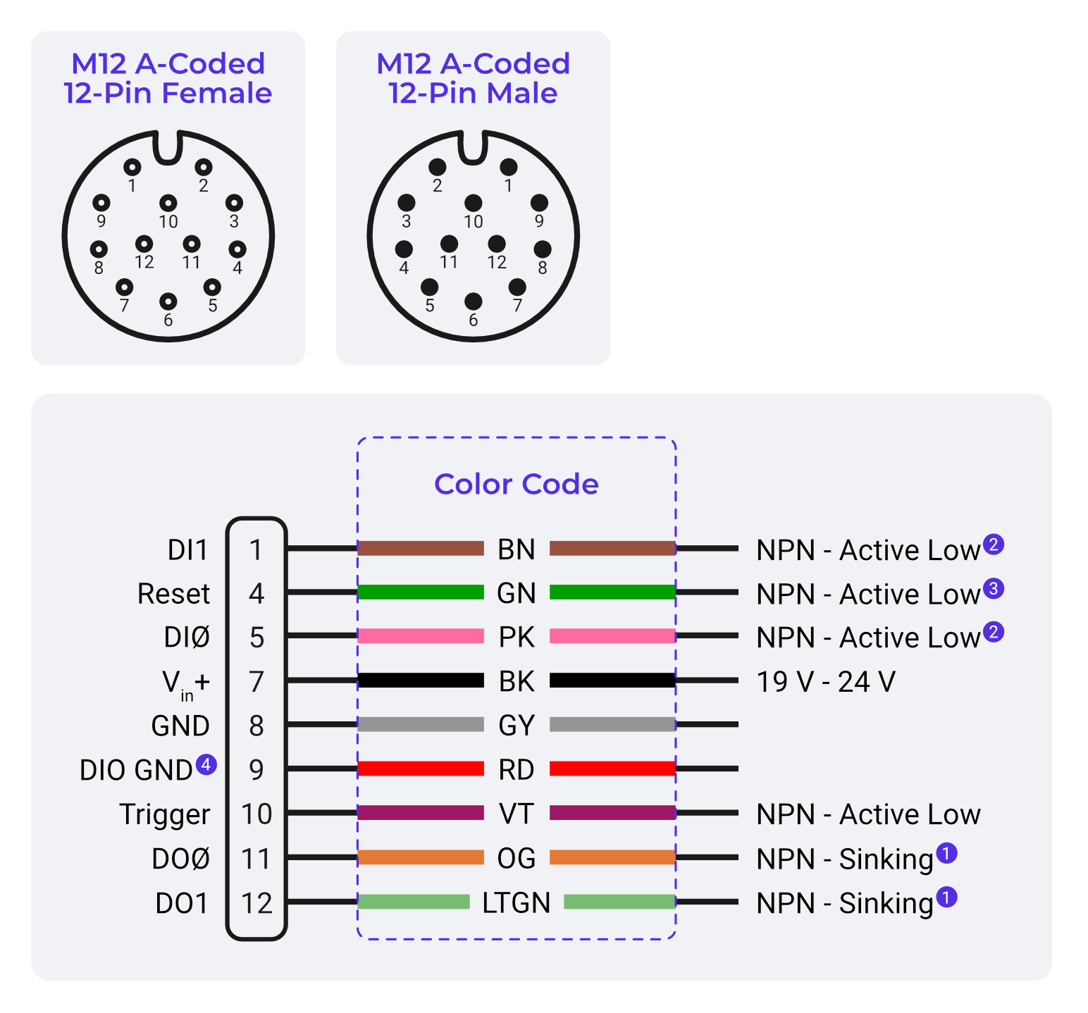
Power and I/O share one M12 A-coded 12-pin connector. On the flying-leads cable each signal has its own colour:
| Pin | Wire colour | Signal | Connect to |
|---|---|---|---|
| 7 | Black (BK) | Vin+ | +24 VDC. Required |
| 8 | Gray (GY) | GND | 0 V. Required |
| 9 | Red (RD) | DIO GND | 0 V reference for the trigger, inputs and outputs |
| 10 | Violet (VT) | Trigger | Your trigger sensor, NPN active low |
| 5 | Pink (PK) | DI0 | Digital input 0, NPN active low |
| 1 | Brown (BN) | DI1 | Digital input 1, NPN active low |
| 11 | Orange (OG) | DO0 | Digital output 0, NPN sinking |
| 12 | Light Green (LTGN) | DO1 / Strobe | Second digital output, or strobe for an external light |
| 4 | Green (GN) | Reset | Pull low to reset the camera |
Only Black and Gray are needed to power the camera. Connect the rest only for the signals you use, and insulate the unused cores so they cannot short against anything.
Black (BK) is +24 V and Gray (GY) is 0 V, the reverse of the convention most people carry in from general electrical work. Check each core against this table before you apply power.
Use a regulated 19–24 VDC supply rated for at least 24 W. Full pin assignments, wire colours, input and output circuits, and electrical limits are on the Pinouts page, where a picker lists every core for the devices you are connecting.
Prefer a single cable? OV Spark also runs on Power over Ethernet through the Overview adapter, from an 802.3af or 802.3at port.
4. Confirm the status LEDs
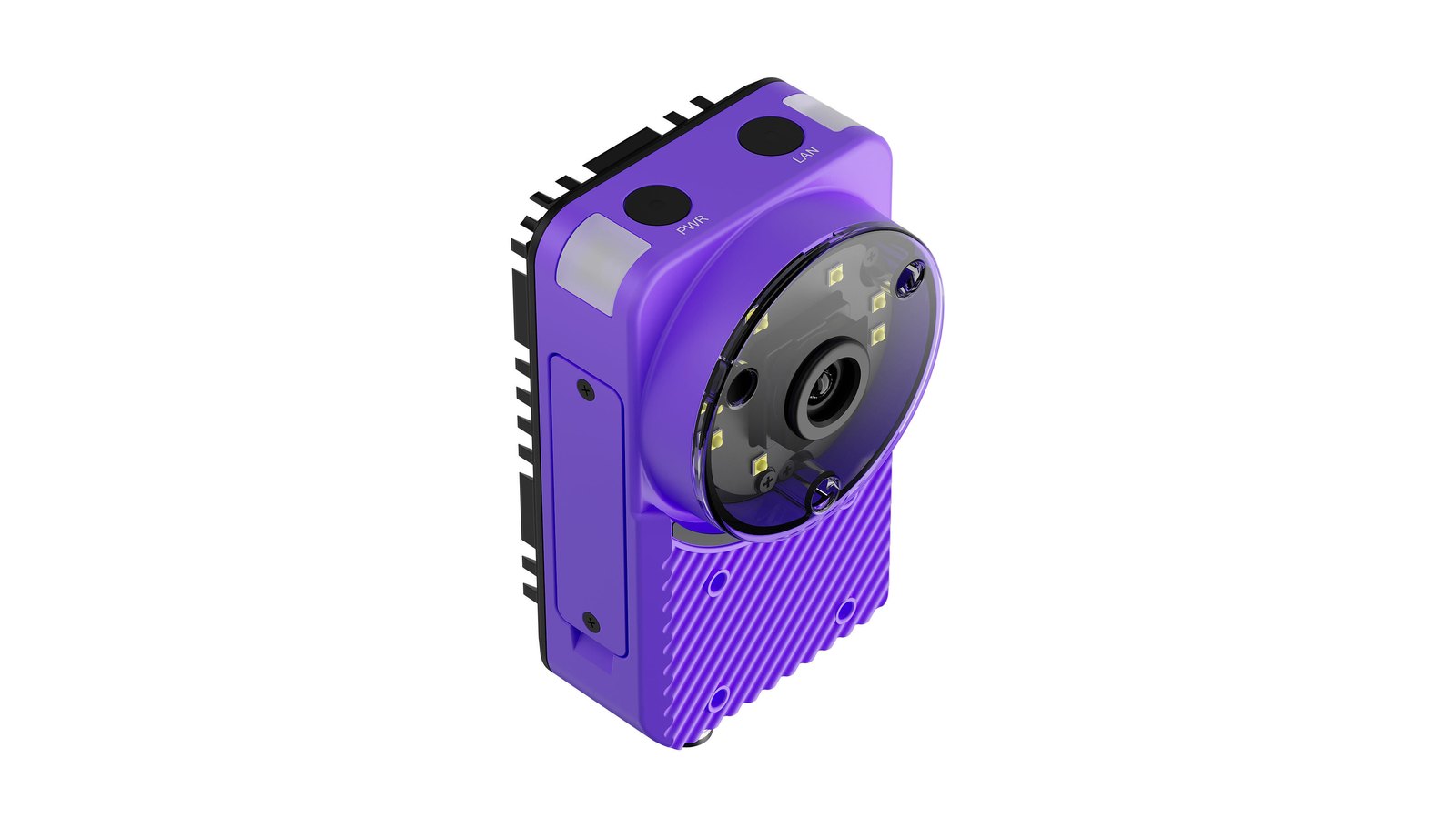
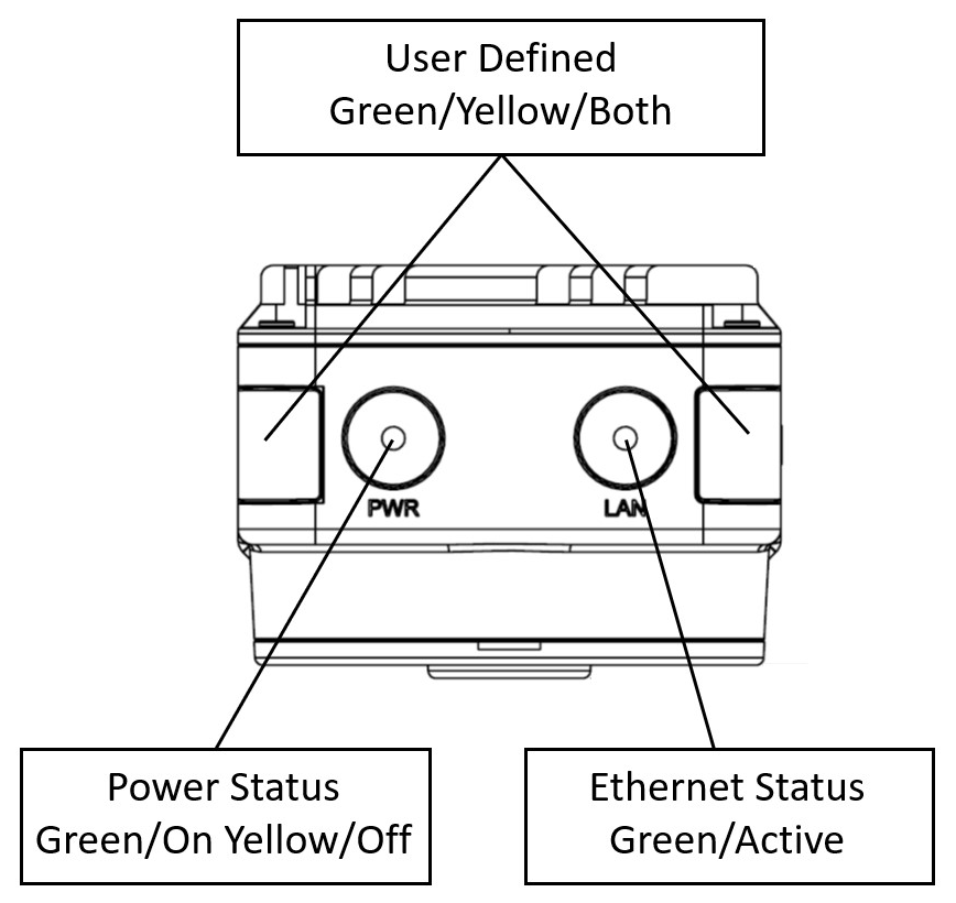
The PWR and LAN indicators are on the top face, between the two corner light bars. The M12 connectors are on the opposite, bottom face.
| LED | State | Meaning |
|---|---|---|
| PWR | Green | Powered and running |
| PWR | Yellow | Powered but off or starting |
| LAN | Green | Ethernet link active |
| Corner indicators | Green / Yellow / Both | User defined, configurable per recipe |
You can set what the corner indicators show in System Settings → General → Indicator LED: either device status, or the inspection result.
If neither LED comes on, check the supply at pins 7 and 8 before suspecting the camera. A supply that sags under inrush current will fail to boot the camera without ever showing a light.
5. CAD models and 2D drawings
Overview provides a 3D model (STEP) and a 2D dimensioned drawing (PDF) of the camera and of each of the three mounting brackets. Use them to design a mount, check clearances, and confirm the field of view before you cut any metal.
Desktop required for CAD downloads
3D CAD models (.STEP) are available for download when viewing on a desktop computer. These files require CAD software to open.
The camera
| File | Format | Size | Description |
|---|---|---|---|
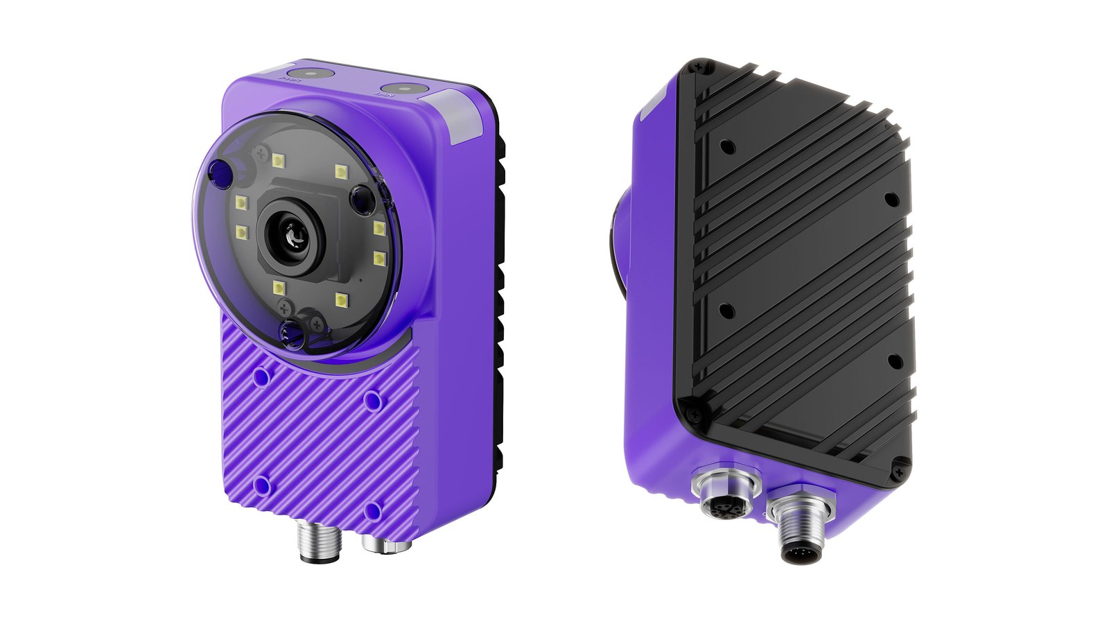
| OV Spark camera | STEP | 22 MB | Full camera assembly, 73 x 134 x 53 mm including the M12 connectors |
| OV Spark camera drawing | 74 KB | Dimensioned drawing, six views, in millimetres |
The body is 70 x 116 x 53 mm, but the model includes the M12 connectors on the bottom face, which increase the height of the camera to about 134 mm (from 116 mm) before any cable is attached. Leave room below for the connector bodies and the bend radius of the cables.
The camera model is a full assembly, so it is large and can be slow to open. If your CAD package offers a simplified or envelope representation, use that for layout work.
Which bracket?
| Bracket | Mounts the camera to | Adjustment |
|---|---|---|
| Bracket 1, adapter plate | A flat surface or machine frame | Slotted holes in the flanges |
| Bracket 2, adjustable stand | A flat surface, standing clear of it | Height, and tilt |
| Bracket 3, rod clamp | A 12 mm rod or post | Position along the rod, and tilt |
Bracket 1: adapter plate
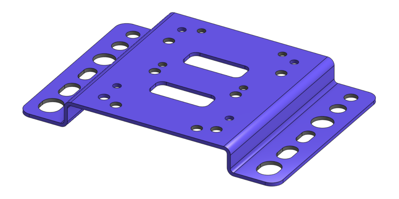
A single stepped plate, 115 x 80 mm with a 12 mm step, in 1.5 mm stainless steel 201.
- The centre carries both OV Spark M3 patterns as clearance holes: 50 x 50 mm for the rear face and 36 x 30 mm for the front face, so the camera can be fixed either way round
- The flanges carry Ø5.5, Ø6.6 and Ø9 mm holes and slots, for M5, M6 or M8 fasteners into your frame
- One part, no hardware. Fix the camera with four M3 screws
| File | Format |
|---|---|
| Bracket 1 model | STEP |
| Bracket 1 drawing |
Bracket 2: adjustable stand
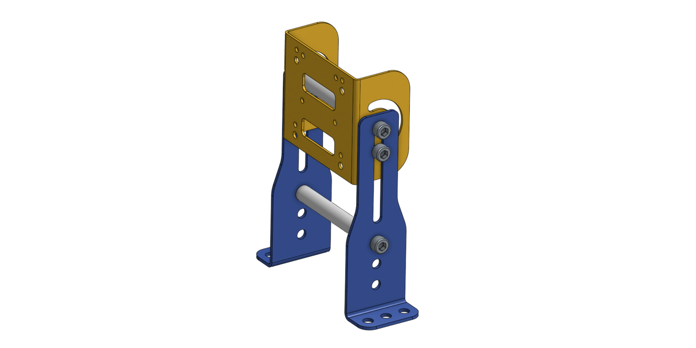
A C-shaped camera plate carried between two sheet-metal legs, joined by two stainless steel rods. Overall 157.5 x 125 mm.
- Height is set by sliding the plate along the slots in the legs
- Tilt is set by rotating the plate on its curved slot before tightening
- The feet carry Ø6.6 mm holes for M6 fasteners
| Item | Part | Qty | Description |
|---|---|---|---|
| 1 | BracketC | 1 | C-shaped camera plate |
| 2 | Leg132-60 | 2 | Sheet-metal leg |
| 3 | rod-10-80-m6 | 2 | Ø10 x 80 mm stainless steel 304 rod, M6 thread in both ends |
| 4 | Hex socket head cap screw M6 x 1.0 x 12 | 6 | |
| 5 | Hex flange nut M6 x 1.0 | 2 |
| File | Format |
|---|---|
| Bracket 2 assembly | STEP |
| Bracket 2 drawing | |
| Rod drawing |
Bracket 3: rod clamp
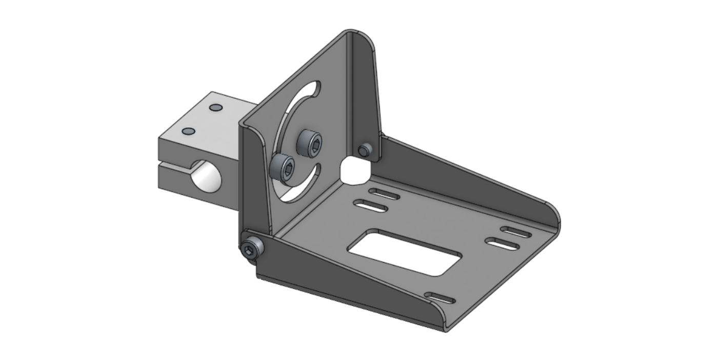
An L-shaped camera plate on a split clamp block with a Ø12 mm H7 bore, for mounting on a 12 mm rod or post. Overall 118 x 85 x 56 mm.
- Slide the clamp along the rod to set the position, then tighten the clamp screws
- Tilt is set by rotating the plate on the curved slot in its upright
| Item | Part | Qty | Description |
|---|---|---|---|
| 1 | BracketL-M4 | 1 | L-shaped camera plate |
| 2 | CLHAM12 | 1 | Clamp block, 12 mm bore |
| 3 | Hex socket head cap screw M5 x 0.8 x 12 | 2 | |
| 4 | Hex socket head cap screw M4 x 0.7 x 6 | 2 | |
| 5 | Hex socket head cap screw M5 x 0.8 x 14 | 2 |
| File | Format |
|---|---|
| Bracket 3 assembly | STEP |
| Bracket 3 drawing |
The tilt on Brackets 2 and 3 is held by friction on the screws. Once the image is set, tighten fully and mark the position. A bracket that creeps changes the image, and a changed image means retraining. See Step 1: Imaging.
6. Connect to the network
Run the M12 Ethernet cable to your switch. Then follow Connect to the interface to reach the camera from a browser.
If you are installing several cameras, or do not know what address a camera has, use OV Configurator to find it on the network. See Connect to the interface.
Installation checklist
- Camera mounted rigidly on the M3 pattern, at a height that gives the field of view you need
- Clear space under the camera for both M12 plugs and their cable bend
- Power wired: pin 7 to +24 V, pin 8 to 0 V, from a regulated supply
- Digital GND (pin 9) referenced for trigger and outputs
- Trigger sensor wired to pin 10 if you are using a hardware trigger
- PWR LED green, LAN LED green
- Camera reachable in a browser