AI-POWERED DOCS
What do you want to know?
Set Digital Output Logic
This guide shows you how to configure the OV20i's digital outputs to control external devices based on inspection results. The camera has 2 digital outputs that operate with True/False logic to trigger sorting mechanisms, indicator lights, alarms, or other automation equipment.
When to Use Digital Outputs: Automated sorting systems, pass/fail indicator lights, reject mechanisms, alarm systems, PLC communication, or any external device that needs to be triggered based on inspection results.
Prerequisites
- OV20i camera system set up and connected
- Active recipe with inspection logic configured
- External device to control (optional for testing)
- Basic understanding of digital I/O concepts
Digital Output Specifications
The OV20i provides 2 digital outputs accessible via the M12 connector:
| Output | Pin # | Wire Color | Function |
|---|---|---|---|
| Digital Output 1 | 10 | Violet | Configurable output |
| Digital Output 2 | 11 | Gray/Pink | Configurable output |
Digital outputs (DO0 / DO1) are NPN open-collector (current-sinking only). An external pull-up or load to +V is required, the outputs can pull to 0 V (ground) but cannot source 24 V.
How NPN Sinking Output Works
Toggle the button below to see how current flows through the circuit when the digital output activates.
Status: OFF
Turn ON the digital output to sink current through the relay coil to ground.
Operating Logic:
- True = Output ON (24V)
- False = Output OFF (0V)
Step 1: Access Node-RED Editor
1.1 Navigate to IO Block
- Open your active recipe in Recipe Editor
- Click Configure IO or select IO Block" in the breadcrumb menu to enter Node-RED editor
1.2 Verify Node-RED Interface
Checkpoint: You should see the Node-RED flow editor with the node palette on the left side.
Step 2: Add Digital Output Node
2.1 Locate Output Node
- Find "Output" node in the left panel (Overview section)
- Drag "Output" node onto the flow canvas
- Double-click node to configure

2.2 Configure Output Settings
Node Configuration:
| Setting | Options | Description |
|---|---|---|
| Output Pin | DO0, DO1 | Select which physical output to control |
| Initial State | OFF, ON | Starting state when system boots |
| Name | Custom text | Optional label for identification |
2.3 Output Configuration Steps
- Select Output Pin:
- DO0 = Digital Output 1 (Pin 10, Violet wire)
- DO1 = Digital Output 2 (Pin 11, Gray/Pink wire)
- Set Initial State:
- OFF = Output starts in OFF state (recommended)
- ON = Output starts in ON state
- Name the Node:
- Use descriptive names like "Reject_Signal" or "Pass_Light"
- Click "Done" to save configuration
Step 3: Connect Logic to Output
3.1 Basic Pass/Fail Output
For simple pass/fail indication:
- Add "Final Pass/Fail Output" node (if not already present)
- Connect: Final Pass/Fail → Output Node
- Result: Output activates when inspection passes
3.2 Inverted Logic (Fail Signal)
To trigger output on inspection failure:
- Add "function" node between pass/fail and output
- Configure function node:
// Invert pass/fail signal - ensure boolean output
msg.payload = !msg.payload;
return msg;
- Connect: Final Pass/Fail → Function → Output Node
- Result: Output activates when inspection fails
3.3 Custom Logic from Classification Results
When using classification or other inspection data:
- Add "function" node to convert results to boolean
- Configure function for your logic:
// Convert classification result to boolean
// Example: Activate output for specific class
if (msg.payload.class === "Defective") {
    msg.payload = true;  // Turn output ON
} else {
    msg.payload = false; // Turn output OFF
}
return msg;
- Connect: Data Source → Function → Output Node
3.4 Boolean Conversion Examples
For different data sources, always convert to boolean:
From confidence values:
// Activate if confidence below threshold
msg.payload = (msg.payload.confidence < 0.8);
return msg;
From ROI results:
// Activate if any ROI failed
msg.payload = msg.payload.roi_results.some(roi => !roi.pass);
return msg;
The Output node requires boolean input (true/false). Always ensure your logic produces boolean values before connecting to the Output node.
Step 4: Create Pulse Output (Recommended)
4.1 Why Use Pulse Output
Pulse output is recommended because:
- Provides clear signal indication
- Prevents output from staying ON indefinitely
- Better for triggering external equipment
- Easier to troubleshoot signal timing
4.2 Add Trigger Node
- Add "trigger" node from Function section
- Place between logic source and output node
- Double-click trigger node to configure
4.3 Configure Trigger Settings
Pulse Configuration:
| Setting | Recommended Value | Description |
|---|---|---|
| Send | True | Initial signal to send |
| Then wait | 500ms | Pulse duration |
| Then send | False | Signal after delay |
| Extend delay | Disabled | Don't extend on new messages |
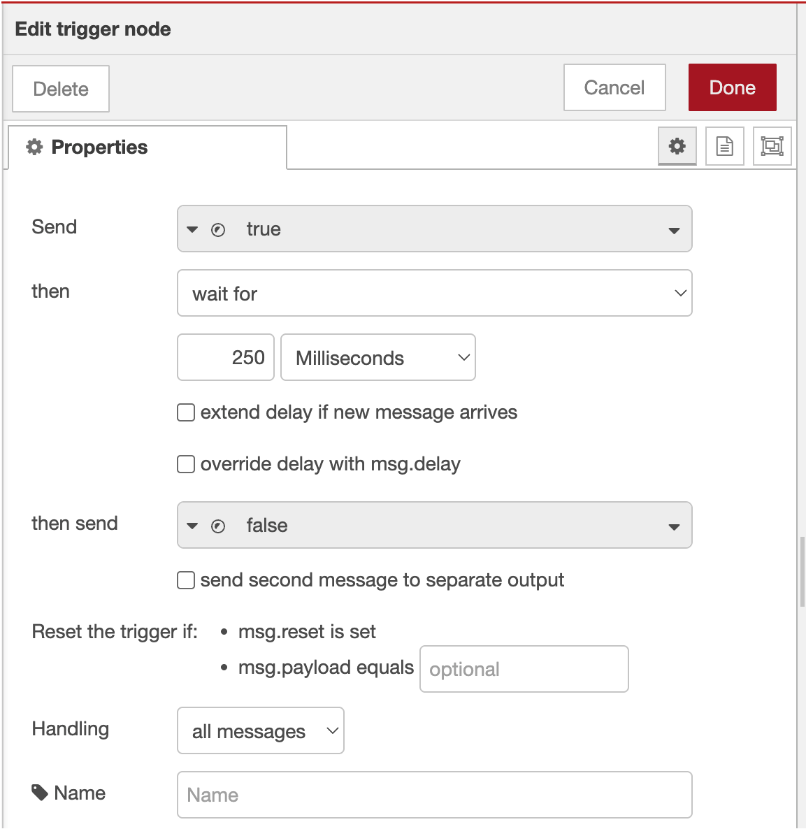
4.4 Trigger Configuration Steps
- First Output:
- Send:
boolean→true - This turns the output ON
- Send:
- Delay Settings:
- Then wait for:
500milliseconds - Then send:
boolean→false - This turns the output OFF after delay
- Then wait for:
- Advanced Options:
- Extend delay if new message arrives: Unchecked
- Stop existing delay if new message arrives: Checked
- Click "Done" to save


4.5 Wire Pulse Configuration
Connect nodes in this order: Logic Source → Trigger → Output Node
Example flow: Final Pass/Fail → Trigger → Output (DO0)
Step 5: Deploy and Test Configuration
5.1 Deploy Flow
- Click "Deploy" button (top-right corner)
- Verify deployment success message
- Check node status indicators
5.2 Monitor Digital I/O Status
Use the built-in I/O monitoring screen:
- Navigate to "I/O Live Monitor" page in main interface
- Observe output status in real-time
- Check "Last state change" timestamps
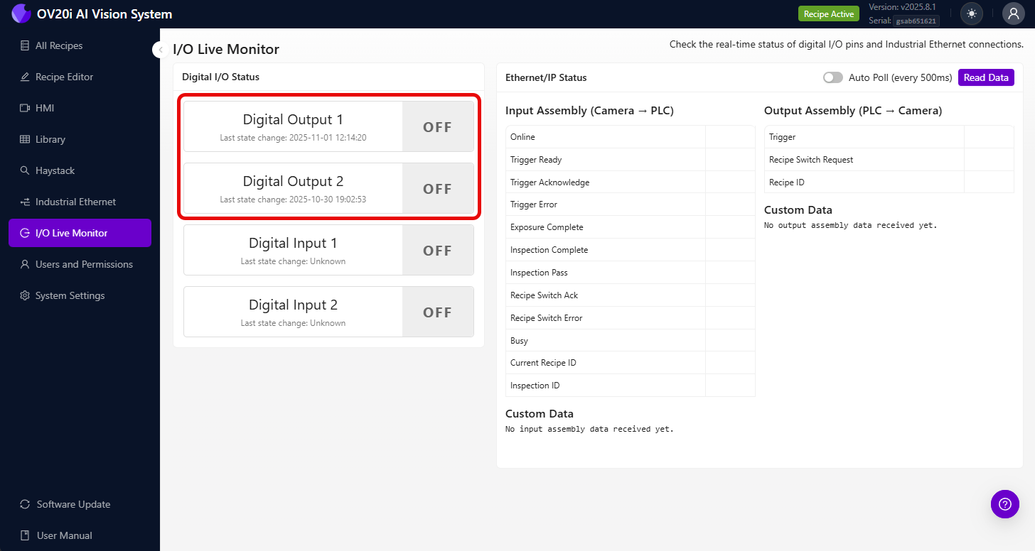
Digtal I/O Status Screen shows:
- Current output state (ON/OFF)
- Last state change timestamp
- Real-time status updates
5.3 Test Output Activation
Manual Testing:
- Add "inject" node for testing
- Configure inject node:
- Payload:
boolean→true - Name: "Test Output"
- Payload:
- Connect: Inject → Trigger → Output
- Click inject button to test output
- Verify output activation in I/O status screen
Step 6: Advanced Output Configurations
6.1 Multiple Output Control
Control both outputs simultaneously:
- Add separate output nodes for DO0 and DO1
- Connect same logic source to both outputs
- Use different trigger delays if needed
6.2 Conditional Output Selection
Route to different outputs based on conditions:
- Add "switch" node from Function section
- Configure routing rules:
// Route based on classification result
if (msg.payload.class === "Large") {
    return [msg, null]; // Send to first output (DO0)
} else if (msg.payload.class === "Small") {
    return [null, msg]; // Send to second output (DO1)
}
return [null, null]; // No output
- Connect switch outputs to respective output nodes
6.3 Delayed Output Sequences
Create timed output sequences:
- Add multiple trigger nodes with different delays
- Configure sequence timing:
- First trigger: 100ms pulse
- Second trigger: 500ms delay, then 200ms pulse
- Connect in series for sequential activation
Step 7: Integration Examples
7.1 Sorting System Integration
Two-way sorting setup:
- DO0 (Output 1): Good parts conveyor
- DO1 (Output 2): Reject bin actuator
Final Pass/Fail → Switch Node → Trigger → DO0 (Pass)
                             → Trigger → DO1 (Fail)
7.2 Alarm System Integration
Multi-level alarm system:
- DO0: Warning light (minor defects)
- DO1: Alarm horn (major defects)
Classification Logic → Function (Check severity) → Appropriate Output
7.3 PLC Communication
Simple PLC handshake:
- DO0: Inspection complete signal
- DO1: Part reject signal
All Block Outputs → Format for PLC → Trigger → DO0
                  → Reject Logic → Trigger → DO1
Step 8: Troubleshooting Output Issues
8.1 Output Not Activating
| Problem | Check | Solution |
|---|---|---|
| No output signal | Node connections | Verify all wires are connected |
| Logic never triggers | Input conditions | Check pass/fail logic configuration |
| Timing issues | Trigger settings | Adjust pulse duration |
| Wrong pin active | Output pin selection | Verify DO0/DO1 configuration |
8.2 Using I/O Status for Troubleshooting
The Digital I/O screen helps identify:
- Current Output State: See if output is actually changing
- Last State Change: Verify timing of output activation
- State History: Track output behavior over time
Troubleshooting with I/O Screen:
- Output shows "OFF" always: Logic may not be triggering
- Output shows "ON" always: Missing pulse configuration
- No timestamp updates: Check Node-RED connections
- Rapid state changes: Logic may be triggering too frequently
8.3 External Device Issues
| Problem | Cause | Solution |
|---|---|---|
| Device doesn't respond | Voltage mismatch | Verify 24V compatibility |
| Intermittent operation | Wiring issues | Check M12 connector wiring |
| Delayed response | External device timing | Adjust pulse duration |
Step 9: Testing and Validation
9.1 Systematic Testing
Test each output systematically:
| Test | Expected Result | Status |
|---|---|---|
| Manual trigger DO0 | Output 1 activates for pulse duration | ☐ |
| Manual trigger DO1 | Output 2 activates for pulse duration | ☐ |
| Pass condition | Correct output activates | ☐ |
| Fail condition | Correct output activates | ☐ |
| I/O status updates | Timestamps show state changes | ☐ |
9.2 Production Validation
Before deploying to production:
- Test with actual parts and inspection conditions
- Verify output timing meets external device requirements
- Confirm electrical connections are secure
- Document output assignments for maintenance
9.3 Performance Verification
Monitor these aspects:
- Response time: Output activation delay after inspection
- Reliability: Consistent output behavior over time
- Timing accuracy: Pulse duration matches configuration
Success! Your Digital Outputs are Ready
Your digital output system can now:
- Control external devices based on inspection results
- Provide pulse signals for reliable triggering
- Support multiple output configurations for complex automation
- Integrate with PLCs and sorting systems for production automation
- Monitor output status through the built-in I/O interface
Ongoing Maintenance
Regular System Checks
- Monitor I/O status screen for consistent operation
- Verify output timing remains within specifications
- Check electrical connections at M12 connector
- Test manual triggers periodically to ensure system health
Troubleshooting Resources
- Use I/O status screen for real-time diagnostics
- Check Node-RED debug panel for logic issues
- Verify external device specifications match output capabilities
- Document any configuration changes for future reference
Next Steps
After configuring digital outputs:
- Set up digital input triggers if needed for external control
- Configure PLC communication for integrated automation
- Implement safety interlocks for production environments
- Create automated monitoring for system health