AI 驱动文档
您想了解什么?
硬件设置与首次连接
本深入指南将对比 OV10i 与 OV80i 相机,概述电源要求、LED 布局以及系统状态指示器,并介绍安装注意事项与最佳实践。
视频指南
通过视频了解此主题:在几分钟内部署 AI 检测
深入指南概览
学习目标
- 连接 → 通电并验证硬件运行
- 激活 → 使相机上线并处于活动状态
- 配置 → 设置网络与系统配置
- 创建 2 个程序 → 构建 classification 和 segmentation 模型
- 构建逻辑 → 使用 Node-RED 实现自动化
您将获得
- 设备相关知识
- 技术信心
- 现场部署的故障排除技能
- 对基本 Node-RED 流程的理解
设备检查
- 相机
- 电源适配器及 M12 电源线 + 以太网电缆
- 样品检测对象
- 文档与快速参考卡
相机型号对比
OV10i - 即插即用解决方案
- 内置 LED 照明,软件控制分区
- 软件控制对焦 - 无需手动调整
- 1.6 MP
- 全局快门
OV80i - 可定制的强力机型
- C 接口镜头灵活性 - 为应用选择最佳光学元件
- 需要外部照明 - 对专用照明实现最大控制
- 8.3 MP
- 卷帘快门
- 更高的处理能力 - 应对复杂的多检测场景
备注
关键物理差异:M12 连接器针脚数量
- OV10i:17 针 M12
- OV80i:12 针 M12
通电
电源要求
- 电压: 19-24 VDC
- 功耗:
- 最大:18W
- 典型:15W
- 连接: 带分线电缆的 M12 连接器
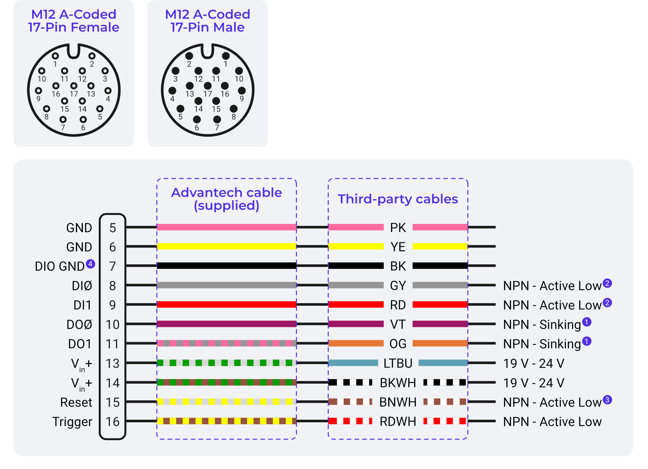
OV10i 电源连接
- M12 17 针连接器连接至相机
- 分线电缆提供独立线缆连接
- 电源端子: 分线电缆上清晰标记 + 与 -
LED 状态指示器与系统健康状况
LED 布局:
- 电源 LED(绿色):指示相机接收到正确的电源
- 网络 LED:显示以太网连接状态
- 状态 LED:系统运行指示器
电源 LED 状态
- 绿色常亮:电源符合规格,相机正常运行
- 熄灭:无电源或电源供电不足
- 昏暗/闪烁/红色: 电源问题 - 检查电压与电流容量
系统状态指示器
- 常亮:系统完全运行,已就绪
- 缓慢闪烁:系统正在启动(前 30-60 秒为正常现象)
- 快速闪烁:系统错误或配置问题
- 熄灭:系统未完全启动或硬件问题
使用 LED 进行故障排除
- 首要检查:在进行高级故障排除之前,始终先验证 LED 状态
- 特定型号:了解每种相机型号上有哪些 LED 处于活动状态
- 远程诊断:LED 可见,便于技术人员通过电话进行指导
- 文档记录:在维护程序中包含 LED 参考说明
物理安装最佳实践
安装选项与注意事项
- 前置安装:相机正面可访问
- 后置安装:保护性更好,更适合恶劣环境
- 减振隔离:必要时使用橡胶垫圈或隔振安装件
- 可访问性:规划清洁和维护的访问空间
电缆布线与管理
- 弯曲半径:遵守 M12 电缆的最小弯曲半径
- 应力消除:使用电缆密封套和应力消除接头
- EMI 注意事项:尽可能远离高功率电缆布线
- 柔性:允许机械运动和热膨胀
环境注意事项
- IP 等级:相机机身按工业环境等级设计
- 清洁:食品级环境可能需要特殊考虑
- 照明:规划环境光对检测的影响
- 温度:在设计中考虑相机的发热