AI-POWERED DOCS
What do you want to know?
Step 2: Triggering
A trigger is what makes the camera capture. Before choosing a mode, check the line will not outrun the camera: this is the single most common cause of rejected triggers and results that lag the part.
Line rate and timing check
Take the inspection time from Processing time in Live Preview or the Library.
Pulses on OV Spark Pro run from 10 to 60000 ms. Twice the scan time is a conservative rule of thumb for an input that is not latched in hardware.
The four modes
OV Spark Pro offers four modes, and manual triggering stays active alongside whichever one you pick, so you can always force a capture while setting up.
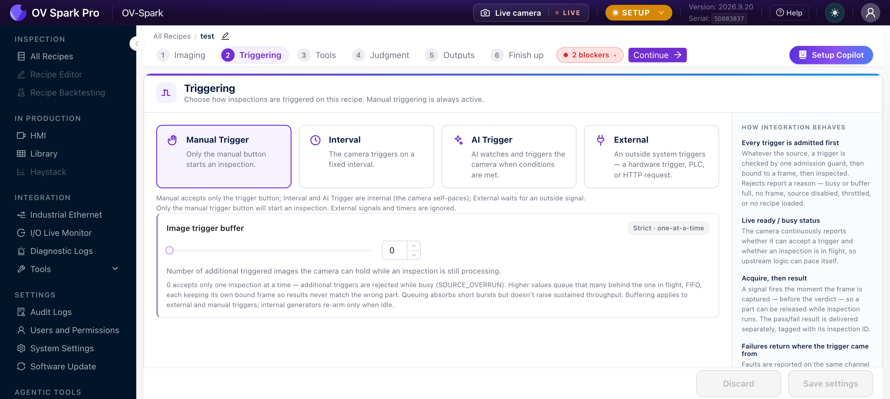
Triggering is Step 2 of the Recipe Editor, so it is set per recipe rather than per camera.
Modes at a glance
| Mode | What fires the inspection | Paced by |
|---|---|---|
| Manual Trigger | Only the manual button | The camera |
| Interval | A fixed time interval | The camera |
| AI Trigger | The camera watches the scene and triggers itself when conditions are met | The camera |
| External | A hardware trigger, PLC, or HTTP request | The outside world |
The first three are internal: the camera decides when to look. External waits to be told.
Which one to use
External is the right answer for most production lines. A part sensor fires as each part arrives, so the capture is tied to the part rather than to a clock. Wire the sensor to pin 10, see Pinouts.
Interval suits continuous processes where there is no discrete part: web inspection, a filled hopper, anything where "every 500 ms" is a more meaningful question than "this part".
AI Trigger removes the sensor entirely. The camera watches for the part to be in position and triggers itself. It is useful where mounting a sensor is impractical, at the cost of the camera continuously evaluating frames.
Manual Trigger is for setup, validation and bench work, not production.
When you choose External, tick the sources the recipe should listen to under Enabled sources: GPIO (a sensor wired to the camera), PLC / Fieldbus, or HTTP (a POST /trigger call from your software, see HTTP API). You can tick more than one. A source that is not ticked is ignored, even if something is sending to it.
AI Trigger in practice
AI Trigger uses an Alignment tool as its evaluator. The camera triggers when that tool finds the part, so the aligner's confidence threshold is also the trigger's sensitivity.
| Setting | Behaviour |
|---|---|
| AI evaluator tool | Which alignment tool decides that the part is present |
| Trigger hold | How long the trigger stays asserted, defaulting to 0 ms |
| Max checks per second | How often the camera evaluates, defaulting to 10 fps |
It fires once when alignment succeeds, holds for the configured time, and re-arms once alignment is lost.
If the recipe has no alignment tool, AI Trigger cannot be saved. See Alignment.
Tuning the aligner's confidence threshold tunes the trigger with it. If you raise the threshold to make the inspection stricter, you also make the camera less willing to trigger at all.
The image trigger buffer
Below the modes is the image trigger buffer: how many triggered images the camera will hold while an inspection is still processing.
- 0 accepts one inspection at a time, and additional triggers are rejected as busy
- Higher values queue triggers, absorbing short bursts
A queue keeps the camera busy, but the result no longer corresponds to the part currently in front of your reject gate. If downstream logic assumes one in, one out, leave the buffer at 0 so an overrun is reported rather than silently delayed.
An overrun you can see in Diagnostic Logs is a problem you can fix. A silently delayed result is a problem you discover from a customer.
Wiring an external trigger
The trigger input is pin 10, referenced to Digital GND on pin 9.
Sensor types and the full circuit are on the Pinouts page. Once wired, use the I/O Live Monitor to confirm the edge is actually arriving before you go looking for problems in the recipe.
Troubleshooting
| Symptom | Where to look |
|---|---|
| No inspection at all | I/O Live Monitor: is there an edge on the trigger track? |
| "Trigger while busy" in the logs | The line is faster than the inspection. See Diagnostic Logs |
| "Trigger not ready" | The PLC is triggering before the camera is armed. Check the handshake in Industrial Ethernet |
| Results lag the part | The trigger buffer is queuing. Set it to 0 |