AI 驱动文档
您想了解什么?
设置数字输出逻辑
本指南将向您展示如何配置 OV10i 的数字输出,以根据检查结果控制外部设备。相机具有 2 个数字输出,采用 True/False 逻辑运行,可触发分拣机构、指示灯、报警器或其他自动化设备。
何时使用数字输出: 自动分拣系统、通过/失败指示灯、剔除机构、报警系统、PLC 通信,或任何需要根据检查结果触发的外部设备。
先决条件
- OV10i 相机系统已设置并连接
- 已配置检查逻辑的活动程序
- 要控制的外部设备(测试时可选)
- 对数字 I/O 概念的基本理解
数字输出规格
OV10i 通过 M12 连接器提供 2 个数字输出:
| 输出 | 引脚编号 | 线缆颜色 | 功能 |
|---|---|---|---|
| 数字输出 1 | 10 | 紫色 | 可配置输出 |
| 数字输出 2 | 11 | 灰色/粉色 | 可配置输出 |
数字输出 (DO0 / DO1) 为 NPN 开集电极(仅电流吸入型)。需要外部上拉电阻或连接至 +V 的负载,输出可下拉至 0 V(地),但不能输出 24 V。
NPN 吸入输出的工作原理
切换下方按钮,查看数字输出激活时电流如何在电路中流动。
Status: OFF
Turn ON the digital output to sink current through the relay coil to ground.
操作逻辑:
- True = 输出 ON (24V)
- False = 输出 OFF (0V)
第一步:访问 Node-RED 编辑器
1.1 导航到 IO模块
- 在程序编辑器中打开您的活动程序
- 点击 Configure IO 或在面包屑菜单中选择 IO Block,进入 Node-RED 编辑器
1.2 验证 Node-RED 界面
检查点: 您应该能看到 Node-RED 流程编辑器,左侧为节点面板。
第二步:添加数字输出节点
2.1 定位输出节点
- 在左侧面板(Overview 部分)找到 "Output" 节点
- 将 "Output" 节点拖动到流程画布上
- 双击节点进行配置

2.2 配置输出设置
节点配置:
| 设置 | 选项 | 说明 |
|---|---|---|
| Output Pin | DO0, DO1 | 选择要控制的物理输出 |
| Initial State | OFF, ON | 系统启动时的初始状态 |
| Name | 自定义文本 | 可选标签,用于识别 |
2.3 输出配置步骤
- 选择 Output Pin:
- DO0 = 数字输出 1(引脚 10,紫色线)
- DO1 = 数字输出 2(引脚 11,灰色/粉色线)
- 设置 Initial State:
- OFF = 输出以 OFF 状态启动(推荐)
- ON = 输出以 ON 状态启动
- 命名节点:
- 使用描述性名称,如 "Reject_Signal" 或 "Pass_Light"
- 点击 "Done" 保存配置
第三步:将逻辑连接到输出
3.1 基本通过/失败输出
用于简单的通过/失败指示:
- 添加 "Final Pass/Fail Output" 节点(如果尚未存在)
- 连接: Final Pass/Fail → Output 节点
- 结果: 检查通过时输出激活
3.2 反向逻辑(失败信号)
在检查失败时触发输出:
- 在 pass/fail 和输出之间添加 "function" 节点
- 配置 function 节点:
// Invert pass/fail signal - ensure boolean output
msg.payload = !msg.payload;
return msg;
- 连接: 最终 Pass/Fail → Function → 输出节点
- 结果: 当检查失败时激活输出
3.3 来自分类结果的自定义逻辑
使用分类或其他检查数据时:
- 添加 "function" 节点 以将结果转换为布尔值
- 根据您的逻辑配置 function:
// Convert classification result to boolean
// Example: Activate output for specific class
if (msg.payload.class === "Defective") {
    msg.payload = true;  // Turn output ON
} else {
    msg.payload = false; // Turn output OFF
}
return msg;
- 连接: 数据源 → Function → 输出节点
3.4 布尔值转换示例
对于不同的数据源,始终转换为布尔值:
从置信度值:
// Activate if confidence below threshold
msg.payload = (msg.payload.confidence <0.8);
return msg;
从 ROI 结果:
// Activate if any ROI failed
msg.payload = msg.payload.roi_results.some(roi => !roi.pass);
return msg;
输出节点需要布尔值输入(true/false)。在连接到输出节点之前,请始终确保您的逻辑产生布尔值。
第四步:创建脉冲输出(推荐)
4.1 为什么使用脉冲输出
推荐使用脉冲输出,因为:
- 提供清晰的信号指示
- 防止输出无限期保持 ON 状态
- 更适合触发外部设备
- 更容易排查信号时序问题
4.2 添加 Trigger 节点
- 从 Function 部分添加 "trigger" 节点
- 放置在 逻辑源和输出节点之间
- 双击 trigger 节点 进行配置
4.3 配置 Trigger 设置
脉冲配置:
| 设置 | 推荐值 | 说明 |
|---|---|---|
| Send | True | 发送的初始信号 |
| Then wait | 500ms | 脉冲持续时间 |
| Then send | False | 延迟后的信号 |
| Extend delay | Disabled | 收到新消息时不延长 |
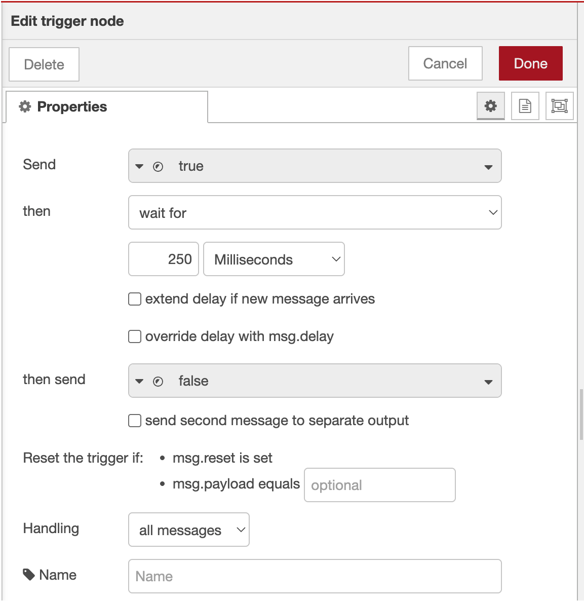
4.4 Trigger 配置步骤
- 首次输出:
- Send:
boolean→true - 此操作将输出置为 ON
- Send:
- 延迟设置:
- Then wait for:
500毫秒 - Then send:
boolean→false - 此操作在延迟后将输出置为 OFF
- Then wait for:
- 高级选项:
- Extend delay if new message arrives: 不勾选
- Stop existing delay if new message arrives: 勾选
- 点击 "Done" 保存


4.5 连接脉冲配置
按以下顺序连接节点: 逻辑源 → Trigger → 输出节点
示例流程: 最终 Pass/Fail → Trigger → 输出 (DO0)
第五步:部署并测试配置
5.1 部署流程
- 点击 "Deploy" 按钮(右上角)
- 验证部署成功 消息
- 检查节点状态 指示器
5.2 监控数字 I/O 状态
使用内置的 I/O 监控界面:
- 导航至主界面中的 "I/O Live Monitor" 页面
- 实时观察输出状态
- 查看 "Last state change" 时间戳
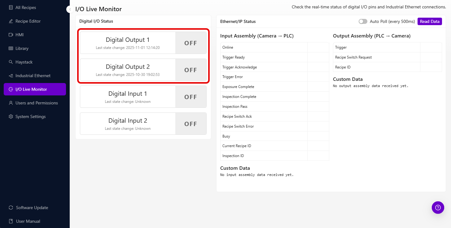
数字 I/O 状态界面显示:
- 当前输出状态 (ON/OFF)
- 上次状态变更时间戳
- 实时状态更新
5.3 测试输出激活
手动测试:
- 添加 "inject" 节点 用于测试
- 配置 inject 节点:
- Payload:
boolean→true - Name: "Test Output"
- Payload:
- 连接: Inject → Trigger → Output
- 点击 inject 按钮 以测试输出
- 在 I/O 状态界面验证输出激活
第 6 步:高级输出配置
6.1 多输出控制
同时控制两个输出:
- 为 DO0 和 DO1 添加独立的输出节点
- 将相同的逻辑源连接到两个输出
- 如有需要,使用不同的触发延迟
6.2 条件输出选择
根据条件路由至不同输出:
- 从 Function 部分添加 "switch" 节点
- 配置路由规则:
// Route based on classification result
if (msg.payload.class === "Large") {
    return [msg, null]; // Send to first output (DO0)
} else if (msg.payload.class === "Small") {
    return [null, msg]; // Send to second output (DO1)
}
return [null, null]; // No output
- 将 switch 输出连接 到相应的输出节点
6.3 延迟输出序列
创建定时输出序列:
- 添加多个具有不同延迟的触发节点
- 配置序列时序:
- 第一次触发:100ms 脉冲
- 第二次触发:500ms 延迟,随后 200ms 脉冲
- 串联连接 以实现顺序激活
第 7 步:集成示例
7.1 分拣系统集成
双向分拣设置:
- DO0(输出 1): 合格品传送带
- DO1(输出 2): 剔除箱执行器
Final Pass/Fail → Switch Node → Trigger → DO0 (Pass)
                             → Trigger → DO1 (Fail)
7.2 报警系统集成
多级报警系统:
- DO0: 警示灯(轻微缺陷)
- DO1: 报警喇叭(严重缺陷)
Classification Logic → Function (Check severity) → Appropriate Output
7.3 PLC 通信
简单 PLC 握手:
- DO0: 检查完成信号
- DO1: 零件剔除信号
All Block Outputs → Format for PLC → Trigger → DO0
                  → Reject Logic → Trigger → DO1
第 8 步:输出问题故障排除
8.1 输出未激活
| 问题 | 检查项 | 解决方案 |
|---|---|---|
| 无输出信号 | 节点连接 | 确认所有连线已连接 |
| 逻辑从不触发 | 输入条件 | 检查 pass/fail 逻辑配置 |
| 时序问题 | 触发设置 | 调整脉冲持续时间 |
| 激活错误引脚 | 输出引脚选择 | 确认 DO0/DO1 配置 |
8.2 使用 I/O 状态进行故障排除
数字 I/O 界面有助于识别:
- 当前输出状态: 查看输出是否真正发生变化
- 上次状态变更: 验证输出激活的时序
- 状态历史: 跟踪输出随时间的行为
使用 I/O 界面进行故障排除:
- 输出始终显示 "OFF": 逻辑可能未触发
- 输出始终显示 "ON": 缺少脉冲配置
- 时间戳未更新: 检查 Node-RED 连接
- 状态快速变化: 逻辑可能触发过于频繁
8.3 外部设备问题
| 问题 | 原因 | 解决方案 |
|---|---|---|
| 设备无响应 | 电压不匹配 | 确认是否兼容 24V |
| 间歇性工作 | 接线问题 | 检查 M12 连接器接线 |
| 响应延迟 | 外部设备时序 | 调整脉冲持续时间 |
第 9 步:测试与验证
9.1 系统性测试
系统性地测试每个输出:
| 测试 | 预期结果 | 状态 |
|---|---|---|
| 手动触发 DO0 | 输出 1 激活脉冲持续时间 | ☐ |
| 手动触发 DO1 | 输出 2 激活脉冲持续时间 | ☐ |
| 通过条件 | 正确的输出被激活 | ☐ |
| 失败条件 | 正确的输出被激活 | ☐ |
| I/O 状态更新 | 时间戳显示状态变化 | ☐ |
9.2 生产验证
在部署到生产环境之前:
- 使用实际部件和检查条件进行测试
- 验证输出时序满足外部设备要求
- 确认电气连接牢固可靠
- 记录输出分配以便维护
9.3 性能验证
监控以下方面:
- 响应时间: 检查后输出激活的延迟
- 可靠性: 输出行为随时间推移保持一致
- 时序精度: 脉冲持续时间与配置匹配
成功!您的数字输出已就绪
您的数字输出系统现在可以:
- 根据检查结果控制外部设备
- 提供脉冲信号以实现可靠触发
- 支持多种输出配置以应对复杂自动化
- 与 PLC 和分拣系统集成以实现生产自动化
- 通过内置 I/O 界面监控输出状态
日常维护
定期系统检查
- 监控 I/O 状态屏幕以确保运行一致性
- 验证输出时序保持在规格范围内
- 检查 M12 连接器处的电气连接
- 定期测试手动触发器以确保系统正常
故障排除资源
- 使用 I/O 状态屏幕进行实时诊断
- 查看 Node-RED 调试面板排查逻辑问题
- 确认外部设备规格与输出能力匹配
- 记录任何配置更改以备日后参考
后续步骤
配置数字输出后:
- 如需外部控制,设置数字输入触发器
- 配置 PLC 通信以实现集成自动化
- 为生产环境实施安全联锁
- 创建自动化监控以监测系统健康状态